Sunday, December 27, 2020

Station 8 - Shafer Prairie

WWSL 1st Subdivision

Location. Schafer Prairie is the first station on the First Subdivision.

Design. Schafer Prairie is the station name for the helix connecting the two decks of the WWSL. 

The helix is a single track main line, with a 21 inch radius, on a 2.38 degree grade, 6 1/2 levels. The helix is visible from one side only, and that side will have scenery and fascia.

Operations. Trains leave Brady Junction and head north on Division 1 trackage toward OPLC Camp 1.

Vignettes.

There are six levels to the helix. For an operator focusing on prototype operation, there is nothing worse than watching a train go round and round on a helix - it challenges the mindset. I decided to establish operational windows that I hope will enhance the operators operational experience rather than distract the operator from the un-prototype length of time the train is out of their immediate vision. Those operational windows I am calling 'vignettes'. These vignettes to will consist of the following right of way scenes:

  • A road crossing. 
  • An absolute stop (ABS) dwarf signal for entry into Brady Junction.
  • A storage track(s) for the WWSL's work train.
  • A cut with embankment to the back of the helix. 
  • A storage track for ballast cars..
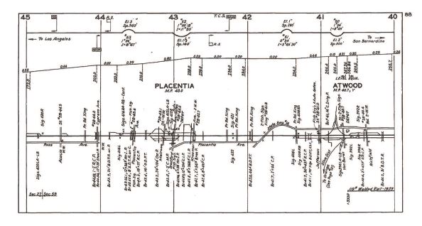
 Track Diagram. 


Roadway. This is the only location on the layout where the roadbed isn't foam. 1/4 inch cork roadbed will be used for the roadbed. 

  • WWSL main line - Class B with relaxed standards
  • WWSL passing track - Class C with relaxed standards

Scenery. Scenery is limited in both the horizontal (30 inches) and vertical (3 inches). 

  • Mid scenery would be primarily cuts and fills with bushes. This scenery would be considered view blocks preventing operators from seeing the non-sceniced interior of the helix. Those view blocks would be removable from the inside for track access as required.
  • Near scenery would be primarily detailed right of way, track and track fixtures, and ballast.
It is anticipated that the vignettes would look something like this: side views of the equipment rather than the traditional 3/4 view preferred by railroad photographers .

(pic)

Catenary/Signaling.  

(C) There is no catenary located within the helix. Catenary poles may be part of the sceniced vignette as warranted. 

(S). There will be an absolute drawf signal on the lower level to control access to Brady Junction.

Rolling Stock. I have envisioned having MOW cars built for operation and display. Those display cars (say 1930's WWSL) would be displayed on those otherwise inaccessible siding tracks. These cars would include single and double sheathed wood outfit cars, truss rod flat cars, wood ballast cars, etc. 

Structures. None

Resource.


Sunday, December 20, 2020

Benchwork is Completed

 This week was the final week of benchwork construction. 

 I cleaned up the rough edges of the valences over the helix.

I purchased and cut to size the 2 inch styrofoam and masonite for the last 4 modules.

I painted the backdrops the two shades of sky. 

I started sorting the bits and pieces of styrofoam in my scrap pile to identify landforms for the WWSL version 3 right of way and toss the rest. Same thing with the lumber shorts. Alot of scrap to the dump. 

Now I have to reorganize again and get the layout room ready for right of way development and tracklaying.


Sunday, December 13, 2020

Station 7 - Wickwood

Location

Wickwood (WK). Location of American Pulp and Paper Mill and the Saginaw Timber Company. Two track yard, RIP track, joint WWSL/OPLC/STC locomotive repair facility. Western Washington Power Company plant spur. Team track. STC engine servicing facility. Interchange with STC .


History


Operations


Vignettes


Highly Desired Elements


Nice to have


Roadway


Scenery


Catenary/Signaling


Locomotives


Rolling Stock 
 
Structures
 
Resources

Sunday, December 6, 2020

Benchwork 10

 Benchwork construction is just about over and I'm glad it's coming to an end. 

Once the helix base was roughed in and emplaced, final benchwork can be completed. 

I installed the south wall upper level horizontal L-Girder. I then installed the east wall upper level horizontal L-girder - completing the upper level benchwork.


I then installed the lower level south wall L-Girder. Notice that I simultaneously installed the east wall L-girder. I had to do this to ensure that the east wall modules were correctly installed at the 8 foot length and whatever excess length of the layout room was reflected in the width of the south wall modules. I anticipated a 32 inch width of the south wall modules. The reality was 33 inches and I'm fine with that.


Not photographed but installed was a lower level leg installed along the south wall to hold up the lower module.


Sunday, November 29, 2020

Station 6 - North River

Location.

The North River is approximately 5 miles south of the MILW/UP main line. 

Vignette. 

Operations. Approaching the North River from the east (actual compass heading is south) the single track WWSL mainline rises along a short fill to cross over the river on a 350 ft long bridge made up of one thru plate girder section on the east side of the river, one steel through truss bridge over the river, and another thru plate girder section on the west side of the river. The west end of the bridge leads to the top of a bluff overlooking the west shore.

Track Diagram
 
(Track Chart)

Roadway.

1 - Stone Abutment
1 - 90 foot Thru Plate Girder Bridge
1 - Stone Pier
1 - 125 foot Thru Truss Girder Bridge
1 - Stone Pier
1 - 90 foot Thru Plate Girder Bridge
1 - Stone Abutment

Catenary/Signaling. None

Scenery

Wide deep river.

References.


Monday, November 23, 2020

Benchwork 9 - Helix

The layout design given and druthers about helixes on a model railroad layout will be discussed in the layout design section of the blog. Here we are going to look at the benchwork construction of the helix base.

The helix module will occupy a space 4 foot long, 4 foot wide and approximately 24 inches or more in height. The sheer size and weight of the module requires some modification of the WWSLs L-girder costruction techniques.

As seen in the lower photograph the major change is the absence of the horizontal 1x3 as part of the lower L girder. A temporary 1x3 was used to ensure level of the horizontal girder and the installation of the backdrop panels.

Next, the helix base was constructed. To minimize weight, I opted to use 1/2 inch playwood for the base. 1x4 inch L-girders were constructed and installed around the outside edges of the playwood panel for strength. L-girders along two edges of the the panel were set in the traditional internal orientation, two L-girders along the other two edges were oriented outward. All 4 corners were reinforced with metal brackets.

Heres a view of the reversed L-girders. In this case the horizontal L-girder members are 1x2 inch dimentional lumber. They are oriented outward so that when the module is installed on the benchwork, the 1x2 horizontal edges hooks onto the benchwork holding it in place until a leg can be temporarily installed, the module leveled and in this case, galanized screws inserted to lock the module onto the benchwork.


Having gotten the base installed with a temporary leg, I then cut the luan panels I plan to use for the helix roadbed to 48x48 inches. I then installed them on the plywood base and aligned them to the base. I screwed them to the plywood base and then sanded the cut edge with a belt sander. 

The lower level has the helix foundation base for stability. The upper level needs a L girder for stability. I used a 2x2 inch stud for the helix leg. I cut the corner of the luan panels and the 1/2 inch plywood panel, placed the leg inside the L-girder corner and screwed it into the L girders.


It is my plan to enclose the helix. The east side of the helix will be painted per the lower level sky color. The north side of the helix will be mostly enclosed as fascia and painted black. To make the backdrop and facia panels flush with the Lgirders at the leg, a 1x3 and 1x2 was attached as trim pieces. 


Now that the helix base is built and installed, I can finish the benchwork in the south east corner of the layout room and call benchwork construction over.

Sunday, November 15, 2020

Station 5 - Preachers Slough

Location.

History. Preachers Slough is the Saginaw Timber Company's connection to the joint UP/MILW mainline.

In the alternate history, when the WWSL acquired trackage south of the Chehelis River from the Saganaw Timber Company, the WWSL built the Chehelis River Bridge. The UP/MILW granted trackage rights from the bridge to MP x where the Saganaw Timber Company had a small interchange yard. That yard became the new interchange yard between the WWSL and the UP/Milw. 

Operations. From the Chehelis River module, the WWSL 2nd Division has trackage rights on the MILW / UP main track from South Montesano to Preachers Slough (not modeled). At Preacher's Slough, the WWSL interchanges with the MILW / UP, then continues south toward Wickwood.

Design.  Preachers Slough is designed to be the interchange point between the WWSL and the MILW/UP.  At the south end of the module, a two track spur diverges from the main track to serve the YKnott Lumber Company tie treatment plant and the Cascade Pole Company

Roadway.

Main track.
Passing siding.
Interchange track

Scenery.

Preachers Slough is designed loosely on three prototype photos I found during my research that appealed to me. 

First was a photo of a Milwaukee road freight coming out of a tunnel. (Location unknown). This will be the south portal of Tunnel 2 on the Second Subdivision.


I really liked this photo of the Milwaukee Road's main track and siding at Pipestone Pass. It merges well with photo 1. This will be the main track and siding, with a third track added to the left for the interchange track. The elevated road will be Highway 107 which parallels the WWSL trackage.


I was trying to figure out what the background should be at the southern end of the module. The hillside with the varied treeline in photo 3 (location unknown) came closest to the Pipestone Pass photo.

Catenary/Signaling. Second Subdivision is non-electrified. 

The real MILW/UP branch line had an automated crossing at Preachers Slough for interchange with the Saganaw Timber Company, as the timber company dumped logs into the Chehelis River at that point for movement to Aberdeen's sawmills. As that crossing is signaled, i will install dwarf signals and they will be operated by the Dispatcher.


Structures. The following structures will be built for the Preachers Slough module:

  • South Portal Tunnel 2
  • Highway 107 Bridge over WWSL main line
  • Interchange shed (MILW/UP)
  • MOW sheds
  • Miscellaneous structures representing the Y. Knott Lumber Company and the Cascade Pole Company


REFERENCES


Sunday, November 8, 2020

Valence 5

This last work session was focused on finishing up bits and pieces of valence and ceiling projects. 

  • Drywall panels that i had delayed putting up were installed in zone 1. 
 
  •  Spackling was done in zone 1, 2 and 3 finishing up ceiling work that had been done in bits and pieces. 
  • The valence extending over the helix was built and installed.


  •  Party light string was installed on the upper valence. 
  • The upper outer l-girder was installed.
 
 
Next week I have to build the helix benchwork so i can finish the upper and lower deck benchwork and call overall benchwork construction done !


Sunday, November 1, 2020

Station 4 - Chehelis River

Location.

2nd Division

History. The original location of an existing Schafer Brothers Logging Company spur line ran from Brady to a two track log dump on the Chehelis River.

The alternate history is that when the WWSL acquired soon to be abandoned trackage south of the Chehelis River from the Saganaw Timber Company to entice the American Pulp and Paper Company to build a mill. The WWSL upgraded the spur line to main line status, built a bridge spanning the Smith Canal, and then built a multi-span bridge across the Chehelis River at its shortest width.

Design. 

Chehelis River is a vignette based on three photos of a bridge.

While reading up on bridges I came across a timber bridge that used retired rails for its stringers. It would work well for the bridge over Smith Canal. 

The single track main track continues on an embankment (the ground along the Chehelis River is flood plain / wetlands /slough)


It then crosses the Chehelis River on a bridge made up of two deck girder bridges and a concrete girder bridge …. and then enters Tunnel S1.


Track Diagram

 Roadway

  •  The WWSL mainline is well maintained main line.

Scenery. The module is a 43 inch x 5 foot outside curve at the end of the center peninsula. The scenery will consist of:

  •  An embankment at the end of the Demaine yard than ends at the edge of Smith Canal.
  • A waterway that begins as a narrow stream (canal) and ends as a small river. 
  • A embankment (levee) that is the roadway for the main line between Demaine Yard and the Chehelis River Bridge.
  • A tunnel that is bored thru a ridgeline that acts as a scenic view block. 
In addition, I'd like to include a second track on the embankment not powered by the layout to act as the programming track for the DCC system. (The DCC system is located directly under this module).

 Catenary/ Signaling

Catenary/Signaling. Second Subdivision is non-electrified. 

Assuming trackage rights on the real MILW/UP branch line, it would make sense that there would be an automated system. There was an automated crossing at Preachers Slough for interchange with the Saganaw Timber Company. Using that system, I will install dwarf signals just before the Chehelis River bridge and they will be operated by the Dispatcher.

Structures.

  • 1- 65 foot wood and rail stringer bridge with one wood and one stone abutment.
  • 2 - xx foot deck plate girder bridges with a concrete abutment and two concrete piers
  • 1 - 30 foot concrete beam bridge with a concrete abutment.
  • 1 concrete tunnel portal with wings

REFERENCES


Sunday, October 25, 2020

Valence 4

Last week i discussed a change in benchwork, resizing the south wall modules from 24 inches to 32 inches in depth. This change while relatively minor resulted in a whole new problem regarding valence location. 

What I failed to realize was that when the ceiling was installed I ran 1x3s and 1x4s to match drywall panel locations. I did NOT add 1x3s at the valence location points. I had two options: 1) I'd  have to mark the ceiling at 32 inches from the wall and cut out the drywall 3 inches wide along the entire 12 foot valence footprint, install a new 1x3 and then replace the piece of drywall I cut out, or 2) I'd have to estimate the location of each rafter and then use a 6 inch long drill bit to find the real location and then use a longer lag screw to secure the valence to the ceiling. 

Keeping it simple, I quickly installed the east wall valence per normal practice. As i had an 8 inch opening along the south wall ceiling that hadnt been drywalled yet, finding the rafters was no problem - a 4' drywall T square made estimating easier and within an hour i had the valences installed.  I missed a couple of rafters by several inches (laterally) but thats just a couple of holes to spackle and the damage is hidden. 


I then finished drywalling the last bit of ceiling and will hit it with spackle and a paint job next week.

All thats left is a short 4 foot section had to be cut at the new 48 inch location for the helix valence, and then installing the party light strings. 


Sunday, October 18, 2020

Station 3 - Demaine Yard

Location.


History. The area where Demaine Yard is located was originally high ground bounded by the NP main line to the north, a platted residential area to the west, flood plain/slough formed by the Chehelis river to the east, and the Chehelis River itself to the south. An existing Schafer Brothers Logging Company spur line ran from Brady to a two track log dump on the Chehelis River.

In the alternate history Montesano became the Headquarters for the railroad when it was established in 1935. As a common carrier with an increased interchange with the NP, it built an interchange yard at Brady. When the WWSL acquired trackage south of the Chehelis River from the Saganaw Timber Company, the WWSL built the Demaine Yard as its primary freight yard.

Operations.

Demaine Yard is a medium sized classification yard operated under the direction of a Yardmaster under Rule 93. It will support a traffic mix of 4 trains, 2 transfers to interchanges, and an local industry switcher. Approximately 50 cars per day will flow through the yard. Most trains are blocked into lumber and mineral traffic headed north and pulp and paper traffic headed south. Cars destined for local shipment and cars interchanging with the Union Pacific, Milwaukee Road and the Nothern Pacific are also blocked here. 

The Subdivision main lines will begin north and south of the main yard.

Design.

Demaine Yard will have the following capabilities:
  • Arrival / Departure Yard. There will be one arrival track and one departure track. Both tracks will  have direct access to the yard lead. The arrival/departure yard will be electrified.
  • Yard Lead. The yard lead will be sized to handle one 8 car train.
  • Classification Yard. The classification yard will be a 2-track yard that will alternate between north/south trains and MILW/UP and NP transfers.
  • Industrial Track. The industrial track will be the industrial lead to four local industry spurs (coal dealership, a lumber distributor, an oil dealer, a propane dealer). Alternatively it can be used as a classification track.

Demaine Yard will designed along the philosophy espoused by Craig Bisgeier's The Ten Commandments of Model Railroad Yard Design

Nice to have Elements. 

  • 1 team track located alongside the yard lead. A freight shed and/or a loading dock.
  • An engine servicing facility for diesel and electric locomotives.
  • A caboose track
Right of Way. 

Scenery
  • The backdrop will be painted as a Near Trees type format. 
  • The yard will be modeled as a flat yard with an industrial format.
  • The module edge will be yard edge scenery to include drainage and selected small buildings as appropriate.

Catenary/Signaling. The arrival and departure tracks, the track leads to the engine service area and Montesano Junction are under wire. Demaine Yard itself is not under wire, nor are the industrial tracks or auxillary tracks.

Locomotives. The Demaine yard switcher will be an ALCO hp switcher. First Subdivision trains will be run with electric locomotives, Second Subdivision trains will be run with diesel locomotives.

Rolling Stock. Unique rolling stock required by the Demaine Yard operations includes:
  • Sand car if engine servicing facility is installed.
  • ICC Type 103 tank cars for fuel distributor.
  • ICC Type 104 tank cars for freight station/team track.
  • ICC Type 105 tank cars for propane distributor. 

Buildings

  • Freight Station
  • Car Repair Shop
  • Coal Dealer (O.McDonalds Coal Co.)
  • Lumber Dealer (Planck's Lumber)
  • Fuel Distributor (Caster Oil Co.)
  • Propane Distributor (Buyher Propane)
  • Arrival Track Buildings
 
References.

The Ten Commandments of Model Railroad Yard Design


Sunday, October 11, 2020

Benchwork 8

The last major section of benchwork to be installed was along the south wall. I knew this was going to be something out of the ordinary because this was new construction per se. All previous benchwork came from WWSL version 2 and was pretty simple to build and install. This section was unique in that it was the location of the helix, and helix construction causes all sorts of benchwork issues. 

Undaunted I forged ahead. The valence along the south wall in zone 3 was built. I initially planned to continue the benchwork at 24 inches in depth leaving an 8 inch gap between the layout and the south wall. Sanity quickly overwelmed me as i realized two things: 1)  an 8 inch gap either requires another stud wall, or 2) i would have to divide two 8 foot modules and insert a special 8 inch module piece somewhere along a straight track sectionso if i ever moved, i would not have to rebuild multiple curved track. Neither solution was appealing to me. 
 
I came to the conclusion that I could use that 8 inches to solve some layout issues I had with the Lumber Camp and the NP interchange yard. (More of that later in the layout planning blog). The 4 modules on the south wall would be 32 inches in depth rather than 24. Up went the standard compressed stud wall, the lower L-Girder, and the backdrop panels. 


At this point I need to reverse my normal installation practice. Previously the upper deck was installed first and the lower deck last for ease of installation. This time around the helix base has to be built and installed, then the lower deck built and installed. The upper deck was then gets measured and installed temporarily - knowing final installation was dependent on the location of the helix exit point. 
 
Helix building is a whole new subject that i will get to shortly. .


Sunday, October 4, 2020

Station 2 Montesano

Main Headquarters

Location. Montesano is the first station south of Brady Junction. 


History

Montesano is a freelanced station on the WWSL. The area was originally high ground bounded by the NP main line to the north, a platted residential area to the west, flood plane/slough formed by the Chehelis river to the east, and the Chehelis River itself to the south. An existing Schafer Brothers Logging Company spur line ran from Brady to a two track log dump on the Chehelis River.

In the alternate history Montesano became the Headquarters for the railroad when it was established in 1935. As a common carrier with an increased interchange with the NP, it built an interchange yard at Brady. When the WWSL acquired trackage south of the Chehelis River from the Saganaw Timber Company, the WWSL built the Demaine Yard. The WWSL headquarters building is mileage 0.0 on the timetable.

Design Considerations.

I saw the Brady Junction - Montesano - Demaine Yard modules to be what a Class 1 railroad would consider to be a Division Point, that is all operations start at this location and extend outward. As a result, we have a major junction, an administrative building/passenger station, an interchange yard and a classification yard in easy communications reach of headquarters. 

The Montesano module ties everything together. One track (normally called the main track) extends north and east to the NP Junction at Brady and WWSL Subdivision 1and south and west to Demaine Yard and the Second Subdivision. It also acts as the station track for passenger operations, and has a turnout that provides passenger car movement from the coach yard to the station.

A second track acts as a the interchange yard lead track. It has turnouts supporting two MOW spurs.

Roadway. 

  • WWSL main track - Class B standard
  • WWSL interchange lead track - Class B standard
  • 2 spur tracks - Class C standard

Catenary/Signaling

  • (C) Main track and coach yard lead are wired.
  • (C) Interchange lead track is not wired.
 Scenery.
  • Background is ground level sparse near treeline.
  • Midground is Headquarters Building
  • Foreground is spur tracks with MOW storage areas.

Rolling Stock 

The option to locate a passenger station to the layout would then entail the acquisition of passenger coaches. See Passenger Car history for additional details.

Structures.
Structures located at this station will be: 

  • Headquarters building is home to WWSL corporate functions. The building also functions as the passsenger station. A building that caught my interest years ago is a C&O Railway building in Thurman WV.
  • A rail and tie storage yard.
  • A bridge parts yard. 


Wednesday, September 30, 2020

Layout Room Cleanup

 Well its fall and time to head back to the layout room and continue the hands on railroad modeling experience. 

As you have been checking out my construction blog posts its very obvious by the pictures that im not a neat freak. I'm pretty messy in fact and I cant tell you the number of times I've shifted construction material etc back and forth in the basement as I progress around the walls. 

When last i spoke of construction back in June, the north (left) side of the layout had been completed ... stud wall, backdrop, valence, upper and lower deck l-girders and module renovation and construction. I got a number of storage shelves and cabinets installed and painted, and have started sorting, organizing and more importantly throwing scrap material out that I cant use or I dont need anymore. 


As you can see its gotten a whole lot cleaner - and just in time to start right of way construction! 

I also did some electrical work as well, finishing the installation of outlets around the perimeter and getting all the new lighting wired to the circuit breaker. This then allowed me to finish drywalling the ceiling in zone 1 (also known as the workshop and crew lounge.) Using this area as the final costruction zone (cutting and assembly etc) will keep the rest of the layout alot cleaner and better organized.


Sunday, September 27, 2020

Layout Details - Construction Overview

Layout Details. Layout details identifies the specifics xxx. It is broken down into two main elements: 5) track planning and 6) construction. Construction consists of four subsets:

a. Human Factors. This basically answers what you want your layout room to be able to do when you are finished.

b. Lighting and Electrical. This section identifies the general and layout specific needs in terms of lighting and electrical.

c. Room Preparation. This identifies the deconstruction and construction to be done's (TBD) that need to be done.

d. Benchwork. Finally! When everything else is done, this section identifies what type of benchwork needs to be constructed.
 
Human Factor. Here are the areas for consideration. 
  • Access to Utilities. Access to set tub, washer and dryer connections. Access to electrical panel, basement drains, and water meter. Access to furnace and water heater. Here were my utility locations. 
  • Crew Lounge. A crew lounge was a luxury I wanted, even though I am a lone wolf modeler. I anticipate recruiting a crew and opening the layout to tours at some point of  time. Combining the Crew Lounge and the Utilities area made alot of sense!
  • Good Storage. I wanted a lot of general storage under the layout.

  • Large Aisles. I'm NOT a fan of small aisles. Been there done that. I like large open areas to work and move through.
  • Clean area. Drywall ceiling, painted walls, and indoor outdoor carpeting.
Lighting and Electrical
 
  • Good Lighting. The original basement had 4 100 watt light bulbs. I wanted 4 total general  lighting zones in the basement, and and an outlet for each of my layout lighting zones. I needed to add nine light switches to control all the lighting zones.
  •  
  • Improved Electrical. There were only two wall outlets in the original basement configuration. I wanted at least two outlet boxes on each wall. I added 6 circuit breakers to my circuit breaker box in anticipation of layout lighting and power needs. 
Room Preparation. 

Deconstruction of the layout space. This is what I had when I went downstairs to the future layout room: Layout Room (Before)

Constructing the layout space.  There is a theory of construction. Of course I didn't follow the construction concepts below for a variety of reasons, including stupidity. If you want to see what not to do read my construction articles beginning here Room Preparation.

  • Empty the space. Working around storage piles, etc is counter-productive time wise.
  • Start at the top and work your way down. This means install all the electrical and lighting in the ceiling, add whatever cable or plumbing requirements, etc.
  • Drywall the ceiling. I found based on my existing basement height, and my desire for valences, that a drop ceiling would not be ideal. All major plumbing raceways are open to repair - the raceways are covered with luan plywood for ascetics. 
  • Work from the outside of the space to the inside.  Fill all cracks in the wall as required. Paint the concrete walls with waterproofing paint.
  • Build interior stud walls (outside walls first, then interior walls).
  • Add electrical and cable wall outlets as required.
  • Drywall as desired.
  • Carpet the floor.

Benchwork
 
WWSL vers.3.0 is salvaged from vers 2.0. I will be using a stud wall, L-Girder frame work and panel type benchwork. See 3.0 Construction for specific details

Station 1 - Brady (BJ)

Location.

 
Brady is (was) a farming community, formerly a logging town, four miles northeast of Montesano in southeast Grays Harbor County on the Satsop River. In 1917, the name Brady was given by Northern Pacific Railroad Company in honor of Emily Brady, from whom a right-of-way had been acquired. Earlier names were Woods (Wood’s) Crossing and Juno (not to be confused with Juno in Whitman County, Wash.

History.

Brady was home to the Schafer Brothers Logging Company. They had a 8 track logging yard located north of the NP main line, a main line that ran north into the timber, an automated crossing of the NP main, and a spur that ran south to a two track log dump adjacent to the Chehelis river where log rafts were constructed and then floated down to sawmills in Hoquiam/Aberdeen Wash.

The Northern Pacific employee timetables listed a 75 car siding at Montesano, Washington, located downtown at the depot. They also list a 10 car commercial spur at Brady for interchange with the Shaefer Logging Company, however the plat map of Brady does not show it clearly.


The alternate history expands this location from a commercial siding and controlled crossing to a junction. The junction consists of the NP main line, the WWSL main line and a NP controlled crossing of the NP main line. A separate track would act as an interchange lead track to a multi-track interchange yard. 

Operations. 

By convention and law, a railroad wanting to cross over another railroad at grade would be responsible for operating the junction and paying the annual operating costs, (maintenance and personnel costs). Originally the NP had an automated crossing at Brady. With additional traffic over the crossing based on the alternative history, a junction tower would be established at Brady Junction to control the junction. That tower and its corresponding equipment would be built and maintained by the WWSL.

Design Considerations.

This module opens up alot of opportunities in its design. It is a real place, it serves as the main interaction point with the outside world (in particular the Northern Pacific Railway), and it is the one point that actually has signalling!

I have decided to attempt to render the NP portion of the module as best as possible. This means I should if possible include:
  1. Olympic Highway (selectively compressed) behind treeline.
  2. NP boundary fence - 4 strand wire 
  3. NP Main Line with non-operational Semaphore Signals. The NP main line would be non-operational, it can be used as a photo-staging location for freight locomotives and rolling stock. 

For the WWSL portion I want to include a (one way) operational junction per prototype practices. His would include: 

  1. WWSL Main Line with operational Dwarf Signals that crosses the NP main line.
  2. An interchange track at Brady Junction that connects with the NP Main Line headed east.
  3. A interchange yard. This is the holding area that collects all interchange traffic between the NP and the WWSL and can be used as a storage yard for unassigned empty cars. The yard consists of 6 visible stub-ended tracks and two transversers. Each track is four feet long and can hold 6 cars.
  4. A coach yard.
Track Plan

(place holder)


Roadway.
 
  • NP right of way. I know in my heart that the NP roadway was relaxed standards at best in the mid 1950's. However I think I will portray the NP right of way as well maintained branch line track. I will give an example of Class 1 roadway to operators and visitors that will show the difference between Class 1 and Class 3 track.
  • WWSL right of way - second class standard (built in 1935)
  • Interchange yard - third class (dirt)
  • Passing Track - second class standard
Cantenary/Signaling
  • (C) Cantenary on main line, interchange yard lead and wired coach storage track.
  • (S) NP Main Line with Semaphore Signals
  • (S) WWSL Main Line at junction with Dwarf Signals.
  • (S) WWSL Dispatcher will act as the WWSL Towerman for purposes of signaling. Signal system will be activated through DCC accessory decoder.
Scenery. 
 
Topographical maps of the Brady area show a wide range of moderate hills north of the Northern Pacific main track. I googled Brady Washington and found that the area was mostly flat with distant hills in the background. I will be paint the background so it looks something like this:


If you have never traveled the Tacoma - Centralia WA area you wouldn't know that Mount Ranier (an extinct volcano) is such as visible landmark for a large number of miles. When in the service at Fort Lewis I  lived in the Bachelor Officers Quarters), I had a 'get out of bed morning view' of the Mount Ranier. Mount Ranier can be seen from the Montesano area and I will use this picture as a painting guide for the east end of the interchange yard backdrop.

Locomotives. The NP motive power at Hoquium in 1955 was a GP7.  I am not sure the specific number stationed there but some research will allow me to model the locomotive for layout photography purposes.

Rolling Stock. The NP used cabooses at the end of their locals. I have identified two cabooses stationed at Hoquium - 1522 and 1663, each a different type, so I will model both for layout photography purposes

Structures.
 
Structures located at this station will include:
  • Junction tower
  • Junction signalling equipment
  • MOW sheds
  • Coach yard service facilities
  • Car inspection facilities
 
PRINT REFERENCES

Montesano area topographic 1940

Northern Pacific Employee Timetable and Special Instructions
 
Brady Plat map


Sunday, September 20, 2020

Layout Design - 6 - Station Maps

In Layout Design Process 4 - Railroad Modeling I identified that the layout design process can be broken down into three primary functional areas: Concept, Structure and Layout Detail.

Layout Detail. Layout Detail identifies the parameters within which the layout must be designed. It is broken down into two main elements: 5) Layout Design, and 6) Construction to build the railroad.
  
Under the element Layout Design, the following area is considered: Station Maps.

Prototye railroads use a variety of  maps to identify right of way information: track diagrams, rail and ballast information, drainage, superelevation and grade line, bridge and building, and signal and communications information. If you're fortunate to have chosen a prototype whose historical society has such maps then you are in luck. Here is my interpretatio of railroad information maps.

Engineering Maps. There are multiple examples of engineering maps. Here is one that focuses on survey information of the right of way, the track diagram includes tangent and curvature information and bridge and building information. 


One of the things i found interesting was the surveying data. Railroad engineering maps  apparently do  use civilian surveying datapoints. The route distances are calibrated on official drawings and blueprints using “stations.” These 'stations' (not to be confused with railroad timetable stations) were measured in feet and were measured from a marker placed somewhere conveniently along the line, not always at a division point. Stations are 100 feet in length. Fractions of a station are denoted by the number of feet appended with a plus sign. Thus 320+45 would be 320 stations plus 45 feet or 3245 feet, which is 0.615 mile.My youngest son found this interesting, as he is a surveyor and he uses GPS data sets on a daily basis.

Mileage Maps.  Here is another type of engineeering map. This map focuses on (from top to bottom) track curvature, grade, track diagram, bridge and signal locations and type. If youre modeling a specific prototype location, this information is invaluable.

This mileage map displays similar information in a different format. The explanations legends are a great tool for modelers interested in the multiple types of buildings, bridge and rail used in prototype operations. I'm going to use this bridge and rail info for right of way information within this blog


There are other references to railroad activities . Here is an example of a Sanborne Insurance map that shows an industrial layout. 


 Here is an example of a cantenary engineering diagram. This will be of interest to me as one subdivision of the WWSL will be under wire. 

You're also in luck if youre modeling the early 1900's. Back between 1910 and 1925, the US government required a valuation process for all railroads. Maps were created to document the track alignments, notes were taken on structures, cuts, fills, and bridges, and photos were taken of many structures and bridges. An amazing amount of these historical materials are available to researchers in the National Archives and Records Administration in Washington, D.C.

The WWSL

The WWSL will use what I call a Station Map to consolidate railroad information. The station map of each major location will identify basic historical, operation, right of way, scenery and building elements.  As the layout progresses, the station map will be upgraded with a track diagram and right of engineering information that will meet the standards for the NMRA AP program. The section map may have one or more subsections included in the location. 
 
References

Southern Pacific Right of way and Structural Drawings

Southern Pacific Engineering Drawings


Sunday, September 13, 2020

Layout Design - 5 - Vignettes

In Layout Design Process 4 - Railroad Modeling I identified that the layout design process can be broken down into three primary functional areas: Concept, Structure and Layout Detail.

Layout Detail. Layout Detail identifies the parameters within which the layout must be designed. It is broken down into two main elements: 5) Layout Design, and 6) Construction to build the railroad.
  
Under the element Layout Design, the following area is considered: Vignettes.

A vignette is a scene or a descriptive sketch. It might focus on a single moment or an image, or it may give a particularly distinct impression of a character or setting. A vignette is a snapshot or a glimpse. As a reader, you may get a distinct and rich impression, but you’re limited in terms of what you see or experience.

I have identified several scenic vignettes that I wish to incorporate in the WWSL. These scenes include:

  1. A slough - wetlands area
  2. A tunnel 
  3. A bridge crossing a stream
  4. A bridge crossing a river
  5. A main line weaving its way through a canyon.
 I also have identified people oriented vignettes. These activities fall into the following categories:
  1. Car movement
  2. Locomotive and caboose servicing
  3. Car inspection, repair and rebuilding
  4. Track maintenance

Sunday, September 6, 2020

Layout Design - 4 - Layout Design Elements

In Layout Design Process 4 - Railroad Modeling I identified that the layout design process can be broken down into three primary functional areas: Concept, Structure and Layout Detail.

Layout Detail. Layout Detail identifies the parameters within which the layout must be designed. It is broken down into two main elements: 5) Layout Design, and 6) Construction to build the railroad.
  
Under the element Layout Design, the following area is considered: Layout Design Elements.
  
Tony Koester in the Model Railoroad Planning Magazine 1995 introduced the the concept of Layout Design Elements -  a design technique of identifying a "signature" scenic element of a prototype or prototype scene and building that element in order to capture the feeling of the prototype. Tony developed a Kalmbach Publishing Company book called 'Realistic Model Railroad Building Blocks' in 2005 to further develop this topic.

Primarily focused on the prototype modeler attempting to selectively compress a real railroads main line into a realistic railroad model layout, Tony further suggested that the modeler 'design his layout as a series of connected elements that are visually and operationally recognizable as models of actual places.' The modeler would identify their modeling interests (see Mike Shafers Shafer's Layout Design Guidelines and use maps, track diagrams, photos, etc., to develop the elements to be modeled. 

Since then many railroad modelers have used this technique to design and build their prototype railroad layouts. Daid Barrows in the Model Railroad Planning 1999 and other articles, used layout design elements in his 'Dominos' layout design techniques. 

The WWSL

Connected elements. I found that in designing my layout that developing the layout concept allowed me to make distinctions between the myriad elements of the prototype (e.g., a yard, a station, a junction) i found in my research with the functional layout requirements that might be necessary for a satisfying layout (such as staging, crossovers, runarounds, et al). I collected a set of layout design elements - from a scenic and operational standpoint – prototype towns, engine terminals yards, junctions, industries or scenes that could be compressed and workable for my layout.  

Those layout design elements were classified by right of way, yard, engine service facilities, industrial track layout, and scenic vignettes that were of interest to me.

The WWSL requires the following layout design elements: 

Right of Way

  • Main track. A track, other than an auxili­ary track, extending through yards and be­tween stations, upon which trains are operated by timetable or train order, or both, or the use of which is governed by block signals.
  • Siding *. A track auxiliary to the main track for meeting or passing trains. The timetable will indicate stations at which sidings are located.
  • Junction. A point where two or more railroads are joined.
  • Interchange. The location where railroads transfer freight cars from other companies over their lines. 
  • Crossing *. A crossing is an intersection where one track crosses another track. It may be located at a junction, but not necessarily so.
  • Simple Overhead Wire *.  A system of overhead wires used to supply electricity to a locomotive which is equipped with a pantograph. The uninsulated wire is attached by clamps to closely spaced crosswires supported by poles. Easily confused with catenary systems which use at least two overhead wires.

Yards

  • Arrival / Departure yard (or track). This is a location in a yard where railcars are dropped off by an arriving train or picked up by departing trains  
  • Classification yard *. This is where the railcars are sorted for further movement to other destinations.
  • Scale Track * .

Engine service facility *

  • Steam
  • Electric
  • Diesel 
  • Turntable *
  • Service Pit Track *

Industries

  • Log reload
  • Coal mine
  • Sand and gravel plant
  • Sawmill
  • Logging camp
  • Paper mill
  • Industrial siding *
  • Power plant (Coal Dump Track * and Ash Pit *)

Vignettes

  • Scenic canyon
  • Wide stream 
  • Wide river

The astericks (*) are layout design elements required for NMRA Achievent Award  (Civil Engineer).

I will be addressing the layout design elements process in follow-on blog posts as they appear on the layout.


Sunday, August 30, 2020

Layout Design - 3 - Geography

In Layout Design Process 4 - Railroad Modeling I identified that the layout design process can be broken down into three primary functional areas: Concept, Structure and Layout Detail.

Layout Detail. Layout Detail identifies the parameters within which the layout must be designed. It is broken down into two main elements: 5) Layout Design, and 6) Construction to build the railroad.
  
Under the element Layout Design, the following area is considered: Geography.
 
In Prototype Interest 1 - Choosing a locale I chose the Western Washington - Olympic Peninsula - Grays Harbor County - Montesano area for the Western Washington Short Line (WWSL). 

As discussed in Layout Detail - 0 - Designing the WWSL, the NP, the MILW, and the UP were established in Grays Harbor and were conducting business. The Schaefer Brothers Logging Company located north of the Chehelis River and the Clemons Logging Company and the Saginaw Timber Company south of the Chehelis River in what the Forestry Department names the Vesta-North River Watershed.

Deciding to overlay the Olympic Peninsula Logging Company / OPLC onto the Schaefer Brothers Logging Company right of way places us at Brady, Wash. The Schaefer Brothers right of way crosses the NP mainline at Brady. To the north of the NP mainline was a logging yard and the logging railroad continued north into the timber. To the south of the NP mainline was what appears to be a engine servicing/repair area and continuing south as a long spur terminating at the Chehelis river, where the logging railroad had a log dump.

montesano - brady map

Following the alternative history of the WWSL, Brady continues to be the crossing of the NP by the WWSL, and is upgraded to a junction and interchange. The area between Montesano and Brady and south of the NP main line will be the Headquarters of the WWSL. The WWSL headquarters, arrival, departure and classification yard (Demaine Yard) could easily be located west and south of the junction and NP main line. Montesano will be the official interchange point with the Northern Pacific.

The WWSL will have two sub-divisions. The First Subdivision will begin north of the Brady crossing and will extend into the timber area. First Division will extend trackage rights with the OPLC and have two interchange locations. 

The Second Subdivision will begin south of Demaine Yard, (Montesano) cross the Chehelis River at the log dump site, parallel the shared Milwaukee Road and the Union Pacific Railroad main line, then crosses the shared mainline and continues south along the old Saginaw Timber Company mainline to Wickwood. The WWSL will interchange with the MILW and UP at Preachers Slough, Wash, and the Saginaw Timber Company at Wickwood, Wash.

The WWSL 

I have conducted some research into the topographic, biotic, soil and climatology of the area in order to better scenic the layout. That information is located at: 5.1a Chehelis River Overview , 5.1b Northern Division Overview,  5.1c Southern Division Overvie.

Physical layout

The WWSL is a bi-level layout. The Division Headquarters (Yellow) and the Second Division and the Saginaw Timber Company (Orange) is located on the lower level; the First Division (Green) and the Olympic Peninsula Logging Company on the upper level. 

Here is a basic location diagram of the WWSL as constructed. Station numbers identify the name of the station and its physical location. 

Division Headquarters.

1. Brady (BR). Brady is home to the NP/WWSL crossing. It is also the location of the fiddle yard used to simulate the NP interchange.

2. Montesano (MO). Montesano is the railroad Headquarters.

3. Demaine Yard has a two track arrival and departure yard, a three track classification yard. The Yardmaster classifies North and Southbound WWSL trains, Class 1 transfers, and picks up and delivers cars at local industrial spurs.

Second Division.

4. Chehelis River. A scenic area.

5. Preachers Slough. (PS). Passing siding, interchange with the MILW and the UP.

6. North River. A scenic area.

7. Wickwood (WK). I found Wickwood on a map in Warren Wing's A Northwest Rails Pictorial. Nothing comes up today in a Google search so i suspect it was a Clemens Logging Company town. I substituted the real location of Arctic, Wash. for the fictional Wickwood. Makes a perfect location for a freelanced pulp and paper mill and other railroad serviced activities. Interchange with the Saganaw Timber Company.

First Division.

8. Schaefer Prairie. The helix moving traffic from the lower to the upper level.

9. OPLC Camp 1 (OP). If Clemons Logging Company could have a company town so could the Olympic Peninsula Logging Company. Interchange with the OPLC.

10. Headquarters Junction (HQ).


11. Olympic Peninsula Lumber Company (SM). Location of the OPLC sawmill complex.

12. Tunnel 1 (TU). A scenic area.

13. Polson Canyon (PC).
A scenic area.

14. Satsop River (SR). A scenic area.

15. Basalt (BS). Location of the Basalt Sand and Gravel Company.

16. Coal Grove (CG). Location of the O.K. Coal Company.

17. Reload (RE).
Location of the OPLC Reload #11. Interchange with the OPLC.