In my last post I committed to getting back in the railroad modeling game. But to do that I have to have space to do the 400 (square foot) of small projects to improve my modeling skills.
The good thing about having a basement for the railroad is I have space. The bad thing about having a basement is its a great place to store things .... and I stored alot of things.
- Two rolling caddies of camping gear.
- Five 2 and 3 shelf bookcases for books and obsolete VHS tapes (alot of tapes!).
- Several former bedroom dressers reconfigured for draw spaces.
- Not one, not two, but three car drawers. See 3.14 Car Drawers for further information.
- Three cabinets for storing car kits, structure kits, and scenery supplies.
- Eleven 2 drawer filing cabinets for storing some 50 years of model railroad articles related to every major topic on the reference page sidebar.
Oh ! I forgot to mention the 400 square feet of shelf space that I call the WWSL ver. 3.0.
Lots and lots of stuff. Some organized but it became unorganized as time went on and I wasn't laying track. Other people call that procrastination. I plead guilty (sheepishly).
Well as my friend said ''You can only eat an elephant one bite at a time." So starting at one end, I started the clean up. Lots of clean up. The hardest part was finding the appropriate place to put it. I deliberately didn't take a before picture.
It took a while, and during that time I had to build some storage space that I knew I needed (someday) and that someday arrived.
Half the layout room is cleaned and organized - the half that I'm going to start working on again. As time goes on, the clutter will continue to be contained, organized or gotten rid of.
|
|
|
|
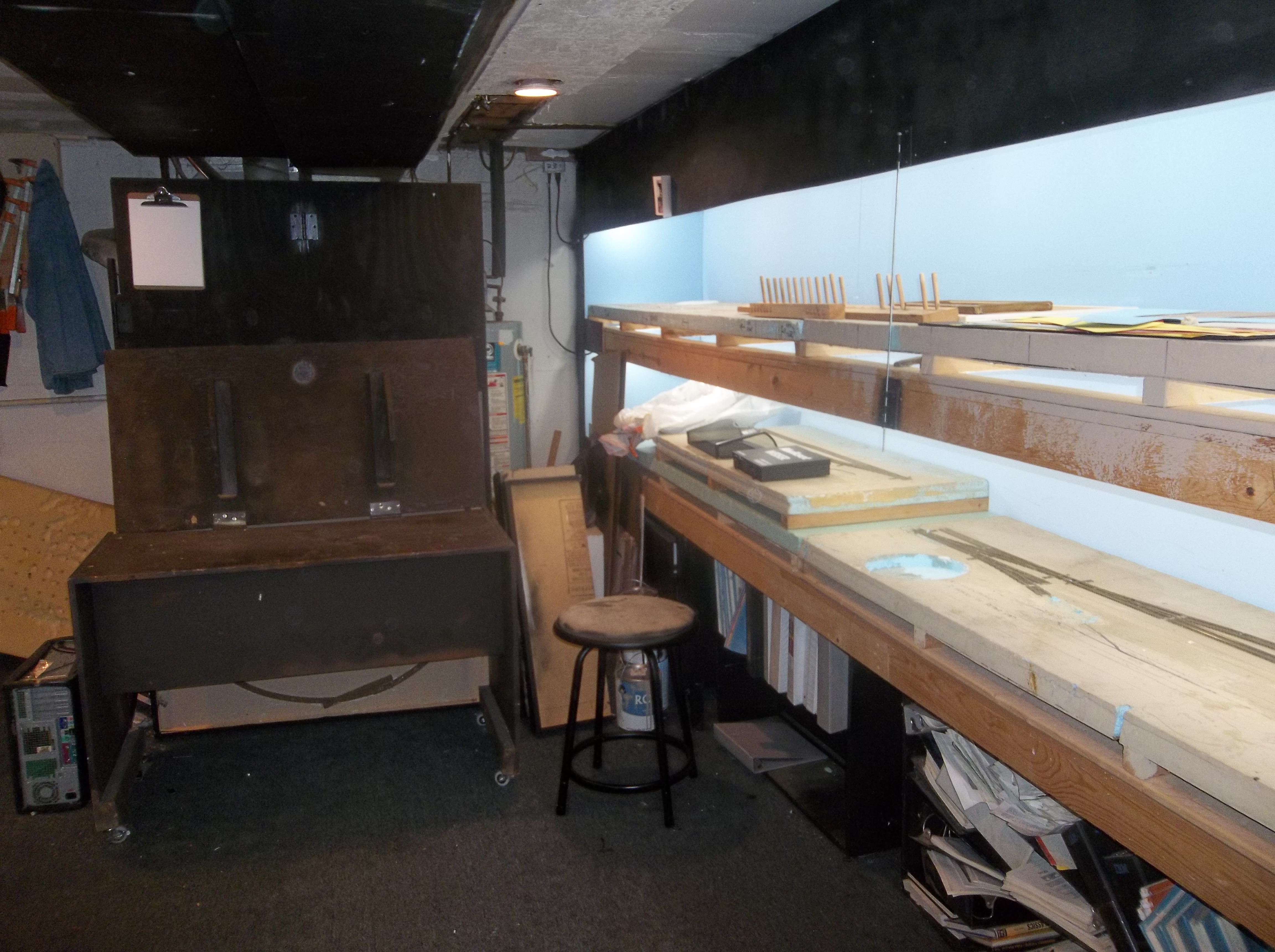


While I was cleaning I decided to fix some of the stationary furniture in the room. The small table is configured as either the dispatcher's desk, or as a drafting table. It's on wheels now for easy moving as necessary.
The two cushion couch was demoted from the living room to the crew lounge / utility room. It will be a nice place to sit when the railroading day is done and I'm marveling at my latest small project success. I ran two 2" x 4"s along the bottom and then put wheels on that so its easy to move from the utility room to the layout space as necessary.
|
|
|
|


"One bite (project) at a time.' Now I have to work on the workshop area to get it organized.