Sunday, June 20, 2021

Layout Design - 8 - Technical Specifications

Prototype Information

A railroad's operations is only as good as its personnel, operating plan, and its physical plant (right of way, yards, locomotive and rolling stock).

In order to ensure that each and every spect of operations is efficient, a series of documents outlining that departments operations is maintained. It is the same with the maintenance of way department.

The maintenance of way department is no exception. The department maintains a series of technical specifications on a wide variety of bridges, buildings, tools and track components used withing the railroad company system.

Fortunately there are two excellent sources of this information on the internet. 

  • Robert Schoenberg maintains a series of Pennsylvania Railroad system Standard MOW plans
  • Don Strack maintains a series of web pages that contains portions of the Union Pacific Common Standards book, a collection includes a large variety standards dating from 1904 to 1985.

Railroads standards were also on occasion mandated by law. I found (somewhere) a consolidated spreadsheet by state and track clearance requirements.

Check out your prototype railroad historical society or web site to see if there are standard plans applicable to your operations.

Modeling Information

The National Model Railroad Association (NMRA) has a series of Recomended Practices (RP) developed for satisfactory model operations based on existing model railroad equipment v. radii of curves and size of turnouts. Those figures, relationships or dimensions were established through actual tests and feel to be beneficial to model operation. 
 
NMRA recommended practices are:  
Andy Hamilton in the February 1991 National Model Railroad Bulletin suggested that Class could be used in the hobby as a means of identifying the look and feel of the layout as it relates to operations, right of way construction and maintenance, locomotive, and rolling stock selection. Andy proposed that Prototype Class 1 operations would be expected to have broad radius curves and high speed (high number) turnouts, compared to prototype Class 3 operations (such as switching lines) that could be expected to have sharp radius curves and slow speed (low number turnouts).

As the WWSL is a Class III railroad, Andy (and the NMRA) would expect it have the following generic technical specification:


Curve standards Sharp (2-8-0)

Turnouts

Trackage

The WWSL

One day the WWSL will maintain a Common Standards book. In the meantime, you'll find those specific standards listed in the WWSL Right of Way Specifications and Modeling section of this web site. 

For general planning and construction purposes:

Human Factors. Here are the human factors used to develop the WWSL layout plan. 

Specification 

In inches

Aisle widths – normal

48

Aisle widths – constrained

30

Benchwork height – upper level

56

Benchwork height – lower level

34

Minimum track setback from Aisle

4

Minimum track setback from wall or backdrop

8

Maximum reach in distance from aisle to track

27

Bench work width for shelf style

24

Module standard width

24

Module standard length

96

Track Planning Standards.  The next step was to develop a set of standards for the trackwork. It would permit operations by virtually all HO scale equipment I would use in WWSL operations.

Specification                                     (In inches)

WWSL

OPLC

STC

Typical equipment length

50


Maximum equipment length


Track centers, double track, tangent

2

2

2

Track centers, tangent, Type 2 cantenary pole


Track centers, arrival departure track


Track centers, yard

2

2

2

Track centers, siding industrial track


Track centers, double track, minimum curve


Turnout number, single

5

6

5

Turnout number, crossover

6

8

6

Turnout number, ladder

5

6

5

Track curve, minimum radius, main line


Track center, double track, minimum radius


Maximum grade %


Vertical curve multiplier


Easement


Super-elevation


Minimum over/under track separation


Sunday, June 13, 2021

Layout Design - 7 - Track Plan Analysis (Part 2)

In Layout Design Process 4 - Railroad Modeling I identified that the layout design process can be broken down into three primary functional areas: Concept, Structure and Layout Detail.

Layout Detail. Layout Detail identifies the parameters within which the layout must be designed. It is broken down into two main elements: 5) Layout Design, and 6) Construction to build the railroad.
  
Under the element Layout Design, Track Plan Analysis (Part 1) considered the design against the layout given and druthers. In Track Plan Analysis (2) will be an analysis of the actual track plan as presently envisioned, and an analysis of operational trackage versus numbers of trains etc.
 
Modeling Information
 
That raised the question about car density on the layout. I found an article in one of the model magazines that discussed a track density study of the model layout. The purpose was to aid the railroad modeler in identifying the following data points:
  • Size of the main line and passing tracks for movement of cars.
  • Functional capacity of cars in yards, industry and storage tracks.

The article provided a spreadsheet format to collect the data. All the trackage on the layout had to be measured by type. Measurement was in 40' carlengths. Those types of trackage to be measured were:

  • Mainline - self-explanatory
  • Siding - Main line passing tracks, not within yard limits
  • Functional - passing tracks within yard limits, yard leads, interchange,
  • Maint/Svc - MOW and engine facilities
  • Yard - tracks not including yard lead
  • Industrial - spur tracks specifically for loading and unloading
  • Storage - All other tracks used to stage or store locomotives and/or cars

Additional operational information is required for analysis. That information includes: 

  • Number of Cars in Service 
  • Number of Cars Moved 
  • InTransit Car Capacity Eastbound
  • InTransit Car Capacity Westbound

Once the data was entered into the database, car density was calculated and compared to a car density baseline suggested by the author. 

  • Functional Mainline Saturation (25-35%). 
  • Functional Track Saturation: (40-50%),
  • Storage Track Saturation: 33% (80-85%) ** assuming class 1 operations
  • Ideal Number of Cars is (30% of Storage tracks filled - Class 3)

The WWSL

An example

Let's use  Station 15 - Basalt for the example. Here is the Section diagram.


Measuring in 40' car length's for each track type we get the following data:


The entire WWSL layout. 

I did this for the entire WWSL layout. The results were:  

My operational information was included:

  • Number of Cars in Service  - 125
  • Number of Cars Moved - 80 (this included OPLC and STC operations)
  • InTransit Car Capacity Eastbound - 36 - (this included OPLC reload operations)
  • InTransit Car Capacity Westbound - 36 - (this included OPLC reload operations)

WWSL Analysis

 Based on the formulas in the spreadsheet, my Track Density for operations were:

  • Functional Mainline Saturation (25-35%) - 53% . 
    • InTransit Car Capacity Eastbound - (25-35%) -27% .
    • InTransit Car Capacity Westbound - (25-35%) - 24% .
  • Functional Track Saturation: (40-50%) - 25%
  • Storage Track Saturation: (80-85%) - 27%
  • Ideal Number of Cars: (30%) - 114
Analysis of the Analysis. I was surprised at how close my initial  layout planning ideas were confirmed by the data analysis.
  • Functional Mainline Saturation (25-35%) - 53% . The WWSL is a Class III railroad and has two additional Class III railroads it provides services to it. The WWSL main line is the means to getting to the customers on the line. 
  • InTransit Car Capacity Eastbound - (25-35%) -27%. This includes the OPLC reload (logging shuttle) operations, some of it on the WWSL main line. Totally consistant with Class III operations.
  • InTransit Car Capacity Westbound - (25-35%) - 24% . Again totally consistant with Class III operations. 
  • Storage Track Saturation - (80-85%) - 27%. Realizing the 80% is assuming class 1 operations, Class III operations would see primarily empty storage tracks as the norm.
  • Ideal Number of Cars -  (30%) - 114. I am using off-layout car storage for additional cars (for purposes of car interchange and car model type variety).
 

Sunday, June 6, 2021

Layout Design - 7 - Track Plan Analysis (Part 1)

In Layout Design Process 4 - Railroad Modeling I identified that the layout design process can be broken down into three primary functional areas: Concept, Structure and Layout Detail.

Layout Detail. Layout Detail identifies the parameters within which the layout must be designed. It is broken down into two main elements: 5) Layout Design, and 6) Construction to build the railroad.
  
Under the element Layout Design, the following area is considered: Track Plan Analysis.
 
The WWSL
 
At this point in time I have collected alot of information through the layout design process. Some of it is here and some is in the Station Plans.
 
Layout givens and druthers.
 
Concept. I am comfortable with the who what where and when aspects of the WWSL version 3.0 I particularly like the idea that i can model the three Class 1's and having the Olympic Peninsula Logging Company and the Saginaw Timber Company live and functioning is icing on the cake.


Operations. I am happy with the freight operations as envisioned. Passenger operations were considered primarily as a mechanism for building a timetable for Master Model Railroader certification. For daily operation, passenger operations is not a priority, it can be done and there are prototype examples for the trains. 
 
I believe that Demaine Yard is designed properly for a Division yard and sized appropriately for the amount of traffic going through the yard daily.

The layout design does address my interests in the natural resources industries. 'Keep it Simple Stupid' was the repeating mantra during the given and druthers stage and I think I've juggled those competing balls adequately. 

Single Track TT&TO operations can be easily implemented. The absence of a complicated signal system is a relief to me. 

An added bonus is the opportunity to model three distinct engine servicing facilities: electric, steam and diesel.


Construction. Fortunately for me I was able to recycle most of the WWSL version 2.0. Benchwork constuction was within my abilities, and new construction was about 25 percent of the layout room. Fourteen modules were reused, 12 modules were built new. 


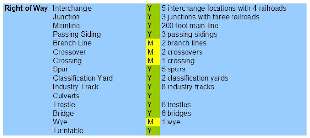
Right of Way.
Double decking the layout was the way to go. I am comfortable with the two heights. The turnout count is high but reasonable given the degree of operating capability. Fine tuned commercial turnouts and flex track will speed up track laying. The track plan will have everything necessary for Master Model Railroader certification. 

The opportunity to build a myriad of bridges, culverts etc. is icing on the cake.
 

Scenery. A majority of the layout is flat, with scenic vignettes having most of the more 'difficult' scenery construction. It is however within my abilities. I'm looking forward to using the more modern scenic techniques employed since my construction of version 2.
 

Catenary/Signal. 
I've opted at this moment in time to model the catenary system minus the actual wire. Its not that im afraid of stringing wire, its the thought of trying to re-railing rolling stock or uncoupling them that gives me pause. Depending on my experience, I may rethink this decision after the majority of the layout is functional. 

Logically it makes sense that a short line would not have any signaling. Research indicates that the NP had an automated crossing with the Shafer Brothers rail crossing at Brady. That would entail semaphores for the NP branch line. I am thinking dwarf signals for the WWSL. The MILW/UP branch line had an automated crossing with the original Saginaw Timber Company. I am thinking dwarf signals for the WWSL there too. I'm looking at a couple of options that could be used to simulate those automated crossings.
 

 Locomotives and rolling stock. I'm looking forward to the opportunities to operate electric, steam and diesel units on the layout. Kitbatching the electric locomotives will be a skill upgrade for me. Steam locomotive operations is new and promising. I have in storage several 2-8-0's and smaller for operations. I've even got a 2-10-2 that could be used. I've got some history to justify it, but its but it's not going to be operational.
 
 
I'm pretty happy at the variety of rollling stock that can be used on the layout. I'm also looking forward to the opportunity to detail existing rolling stock and kitbatching existing cars that cannot be purchased.


Human Factors. I've always wanted a dedicated railroad layout space. Now I have it and it's met my expectations. Its fun to be down there (compared to other locations where I've had my layouts set up).  
 

Only one place has a aisle pinch point that doesn't meet the aisle parameter of a minimum 36-inch width to provide comfortable movement by crew - the right side of the layout where the workbench is located. Moving the center peninsula leftward was considered however the furnace air runs interfered with the possible construction of a stud wall and the two lally columns in the middle would interfere with personnel movement along the right center peninsula.  As it is a quick walk thru area with open space on either end for train control, the pinch point is considered a necessary evil. 
 
Having to duck under to get to the interior of the helix for track cleaning and maintenance is a necessary evil as well. Fortunately I'm still limber! 

Layout Design - 8 - Track Plan Analysis (Part 2) will be an analysis of the operational trackage versus numbers of trains, cars, etc.