Showing posts with label North River. Show all posts

Sunday, January 22, 2023

Section 6 - North River Bridge - Part 2

In the last blog (Section 6 - North River Bridge - Part 1) I identified the layout design elements of the North River Bridge Module and laid out the roadway lines.

In this blog I am identifying the scenery construction concept and laying out the landforms.

As a refresher, here are the scenic elements.

  1. A sunny sky.
  2. A distant treeline with a river disappearing in the distance.
  3. A low dam in the background.
  4. A wide deep river with relatively high river bank.
  5. A lower river area expanding into the delta area. 

Scenery Design Considerations

Background

The backdrop available for the North River Bridge section is 22 inches in height. 


1. A blue sky with cumulus clouds suggesting a sunny day. See 5.4.1 Sky  and 5.4.2 Clouds for construction information.  

2. A distant tree line. See 5.4.6 Closer Hills and 5.4.9 Conifer Trees for construction information.

Landforms

Midground

The right of way parallels the terrain along the ridge line. The terrain on the near side of the right of way has been engineered as an embankment.


Foreground 

The remainder of the forground is open ground, either flat or sloped downward toward the fascia.

Creating the Landforms

Background Landmass

Just like the Satsop River build, I built two small roadbed panels and installed them at the module ends, leaving the center roadway / waterway area clear. 

4. Upper river bank. Upon installation of the dam, the rest of the upper riverbank was fairly straight forward The river bank carved and shaped to about a 45 degree angle. I used a drywall knive and the Stanley Surform scraper for this step. The shreds of foam were messy but easier to clean up than sanding conventional plaster.

5. Lower river bank. The north river bank (right) and the south river bank (left) are manmade embankment. The AREA standard for an embankment is a 60 degree angle from the edge of the roadbed to the river bottom.  See 4.1.1.2 Embankments for construction details. Using to total length of the bridge complex, I will locate the south abutment and cut it in. Pieces of styrofoam and expanding foam will complete the basic landform.

Once I figure out where the bridge abutments are located, I can shape the river and the river banks, adding foam as necessary. The embankments are formed with the 2 inch styrofoam and open spaces under the masonite and above the plywood are filled with 2 inch stryofoam cut to fit, and using expanding foam as necessary.

Once the basic landforms are formed, it will be covered with Sculptamold on the flats and hydrocal plaster on the slopes. 

Waterways

The head dam

3. A low head dam, sometimes simply called a weir, is a small structure that impounds a small amount of water and spans the width of river or stream. Usually made from concrete, the purpose of a low head dam is to raise the water level upstream on a river. In this particular case, the WWSL history has indicated it is one of several dams on the North River that provide a reservoir for American Pulp and Paper Company operations. 

4. The head dam is anchored on the high terrain on either side of the river bank. The river bank has a height of 4 inches, the height of the head dam is three inches.  See 10.xx.xx for construction details.

3. I am currently considering my options for completing the river I haven't decided whether to pour epoxy water or use a combination of paint and matte and gloss medium. Ive got plenty of time to make that decision. By its very nature there will be three techniques used:

  • The upper waterway will be created by  . See 5.8.x Lake for construction details.
  • The water fall over the dam will be created with xxx. See 5.8.6 Waterfall for construction details.
  • The lower river will be See 5.8.4 River (Deep)  for construction details.

 Reference


Sunday, January 8, 2023

Section 6 - North River Bridge - Part 1

It's time to lay out the North River Bridge section. The layout design given and druthers of this section is identified in Station 6 - North River Bridge.

Layout Design Elements

The North River Bridge section adjoins the Preachers Slough section to the north and the Wickwood section to the south. It has seven scenic elements (from backdrop to fascia):

This module consists of eight layout design elements:

  1. A partly cloudy sky suggesting sunny weather.
  2. A mid-distant treeline with a river disappearing in the distance.
  3. A low dam in the background.
  4. A wide deep river with relatively high river banks.
  5. One through truss bridge .
  6. Two through plate girder bridges.
  7. Two stone abutments.
  8. Two stone piers.
  9. A wide shallow river with low river banks.

 Module Construction

See the WWSL module construction reference page for the construction technique. 

As this module is a river module I have modified the construction technique. Instead of using the two 1"x3" girders on the bottom of the module, I need a solid bottom on the module for the riverbed. The 1"x3" girders are replaced by a 2-foot by 8-foot piece of plywood, 3/4 inches thick. The two ends of the module are cut out to permit attachment of the module electrical connectors and module interface bolts. 

The remainder of the module is built per standard WWSL construction standards.


ROW Design Considerations 

The most critical design considerations on this module is the length of the bridge. With only 96 inches of linear space to model two river banks and three bridges, something has to be compressed. 

First I looked at the two curved legs. At Wickwood, the 26-inch radius curve needs to connect to a tangent track located 12 inches from the front fascia. That means that 16 inches of space is needed on this module for the south mainline curve. 

At Preachers Slough, the 26-inch radius curve needs to connect to a tangent track located 16 inches from the front fascia. This means that 10 inches of space is needed on this module for the south main line curve. A total of approximately 26 inches is needed for the curved main line components. That leaves us with 70 inches of tangent mainline track for the three bridges.

4.The through truss bridge is a Central Valley bridge kit. Total length of that bridge will be 21 inches. See 4.1.9.12 North River Bridge S5 (Through Truss (Pratt)) for construction details.

5. The through plate girder bridges are Central Valley bridge kits. Each bridge is 10 inches long, for a total of 20 inches, See 4.1.9.12 North River Bridge S5 (Through Plate Girder) for construction details. With the through truss bridge, the total length is 41 inches -  plenty of room for the bridge.

6. The abutments will will be Chooch stone abutments. They require some modification - the overall height is good but the bridge step needs to be increased to permit the installation of appropriate bridge pedestals. See 4.1.9.12 North River Bridge S5a (Masonry Abutments) for construction details. 

7. The in-river piers will be Chooch stone piers. They require a similar reduction in height only. See 4.1.9.12 North River Bridge S5b (Masonry Piers) for construction details.

Laying out the Structures

I used a pair of 3 foot yard sticks to determine the anticipated length of the bridge complex (53 inches) and for initial siting of the river banks and the bulkhead, piers and concrete abutment.

Essentially you're going to follow this process: 

  1. Lay out the Bridge complex. It will be centered on the module.
  2. Locate the abutments and piers.
  3. Lay out the Dam complex.The dam will be centered and extend approximately 4 inches into the module.
  4. Lay out the river banks

I have considered adding some structures in support of the dam but haven't determined what specifically will be added. See the Structures Reference Page  for the specific details about those structures.

Laying out the Right of Way

I am not going to go into great detail about putting down the roadbed lines. See the Right of Way Reference Page  for the details if you haven't had the fun to do it before. 

Essentially you're going to follow this process: 

  1. Lay out the main line. I centered it at the 12 inch line.
  2. Lay out the main line curves with easements.
  3. Lay out the bridge template, the length of the bridge and adjust as necessary.
  4. Lay out the south embankment leading to the bridges. 
  5. Locate the abutments and pier.
  6. Layout the river banks on either side of the river.

Because this module ties into both the Wickwood Module and the Preachers Slough module some layout of those modules will need to be done at the same time, primarily the main line locator at Wickwood (12 inches from the fascia) and the southernmost Preachers Slough curve (16 inches from the fascia). 

Roadway Details

  • The WWSL 2nd Division is designated Class A main line. See 4.2.11.1  Modeling Technique for High Profile Roadway for details.
  • Bridge Profile.  See 4.2.11.16 Modeling Technique for Bridge Roadway for details.
Right of Way Drainage.  See 4.1.8 Ditches, Drains and Culverts
  • Drainage
  • Culverts

MOW Details

  • 4.2.12.5 Rail Rests
  • 4.2.12.6 Tie Stack Detail

 Track Details.


 .

In the next blog (Section 6 - North River Bridge Module - Part 2) I will discuss the Scenic Design Considerations. 

Reference

See 4.2.3 Laying Straight Track and 4.2.4 Laying Curve Track for construction details.

Sunday, November 29, 2020

Station 6 - North River

Location.

The North River is a river, approximately 30 miles (48 km) long, in western Washington. The river rises in the Willapa Hills in northeastern Pacific County and flows northwest into Grays Harbor County. Much of the North River's drainage basin is within the Clemons Tree Farm in Montesano and it empties into Willapa Bay, a large estuary of the Columbia River off the south coast of Washington.

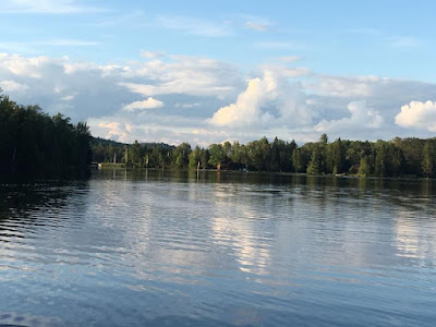
Vignette. The American Pulp and Paper Company in Wickwood needs an abundant of water for its pulp production. The North River could provide that water if strategically dammed. In my deliberations I was influenced by two photographs


 Track Diagram


Roadway.
1 - Stone Abutment
1 - 90 foot Thru Plate Girder Bridge
1 - Stone Pier
1 - 125 foot Thru Truss Girder Bridge
1 - Stone Pier
1 - 90 foot Thru Plate Girder Bridge
1 - Stone Abutment

Catenary/Signaling. None

Scenery. Approaching the North River from the east (actual compass heading is south) the single track WWSL mainline rises along a short fill to cross over the river on a 350 ft long bridge made up of one thru plate girder section on the east side of the river, one steel through truss bridge over the river, and another thru plate girder section on the west side of the river. The west end of the bridge leads to the top of a bluff overlooking the west shore.

References.