Sunday, March 29, 2020

Modeling Interest 2 - Industry

In Layout Design Process 4 - Railroad Modeling I identified that the layout design process can be broken down into three primary functional areas: Concept, Structure and Layout Detail.

Concept identifies the: Who,What,Where, When and Why aspects of the layout development process. In this blog we will discuss the second of the five elements of Concept 2) Specific modeling interests - Industries
 

Industry

Freight cars are loaded and unloaded on four classes of track: industry, freight stations, team and intermodal. This includes heavy industry, light industry and urban industrial areas that allows switching operations. fIn previous blogs we discussed my interest in modeling 1950's Pacific Northwest, particularly Grays Harbor County, WA. Railroads in the County were primarily focused on moving natural resources.   

Lumber. My interest in logging suggests a logging camp and reload facility. Logging industry activities include sawmills, planing mills, chip mills, pulp and paper mills, veneer and plywood mills, pole and wood product preservation companies.

Coal Mining. My interest in coal mining suggests a coal breaker, a sizing tipple, a coal washing plant, and a loading area for multiple sizes of coal.

Sand and Gravel Processing. My interest in sand and gravel processing suggests a processing area for sizing and processing gravel, a second area for sizing and drying sand, and outdoor and silo storage areas for sand and gravel, and a loading area for both products.


For my purposes, I am going to define industry in three types based on the square footage I am going to allot the industry on my railroad: heavy, medium and local switching.

  • Heavy Industry will consist of:1) the logging camp, the reload facility, sawmill planing mill and chip mill, and in a separate location, 2) a pulp and paper mill. 
  • Medium Industry will consist of 3) a coal mine with coal breaker sizing tipple and a loading area, and 4) a sand and gravel processing area with a processing area for sizing and drying sand and outdoor and silo storage areas for sand and a loading area for gravel.
  •  Light Industry will consist of 5) a creosote plant and 6) wood pole distributor.
  •  Light Switching will consist of common small town distributors of coal,lumber, natural gas, fuel and oil.

Freight Stations. 

Freight stations are the railroad owned depots at which less-than-carload (LCL) traffic was received and delivered. While I do not anticipate large amounts of LCL traffic, freight stations are the admin locations of station agents /car distributors who are responsible for car waybilling and customer service.The Northern Pacific maintained a freight station at Montesano, so I would anticipate that any LCL freight for WWSL customers would end up there for delivery. I anticipate having one freight station, primarily for freight administrative operations. As a 'exception to the rule' operation, the station could be used for large shipments transloaded or transferred to the WWLS freight station by truck or interchange.

Team Track. 

Team tracks serve industries which either are not located on the railroad or which receive and dispatch carload shipments too rarely to justify having their own siding. The Northern Pacific had three industry spur tracks and a team track in Montesano and had 6 companies identified as using the track:


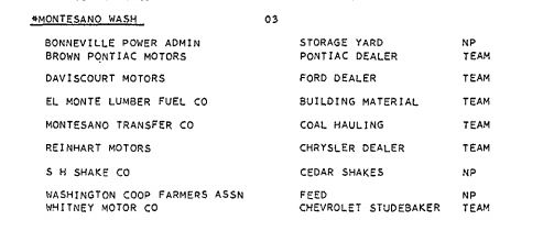
I anticipate having one team track associated with the WWSL freight station. This team track could be used for unusual loads that may be transported to the woods, although i suspect that it would primarily be used by the WWSL for the loading of Christmas trees during the late fall, a seasonal activity done by quite a few railroads serving forest production companies. There would be no overlap of services with the NP team track. 

Intermodal (TOFC/COFC).

TOFC/COFC became a major source of freight traffic around 1960. I have not found any indication of TOFC/COFC operations in the Gray's Harbor region, and do not plan on having said on the WWSL.


Wednesday, March 25, 2020

Lighting 2

Per my comments in Lighting Concepts, I used 48 ft Medium Base String Lights - Black from https://www.partylights.com/48-Medium-Base-Stringer-Black. There are 24 sockets on 24 inch centers in each string.

i began to install Upper Deck String 1. I started at the left end of the north wall valence where i had installed a controlled outlet. I marked each panel at 1', 3' 5' and 7'. Starting at the plug end of the string I installed one base at each mark using two 3/4 inch lath screws.


Each base then had a 9w 5000k LED lamp installed.


I continued to install valence above the east and north center peninsula sections. 


North Wall


The lighting string continued along to where the center peninsula met the east wall. Four bases were installed on the center peninsula valence. They will be cut from the Upper Deck String 1 and spliced into the Upper Deck String 2 after all the benchwork and valences are constructed.


Sunday, March 22, 2020

Modeling Interests 1 - Railroad Operations

In Layout Design Process 4 - Railroad Modeling I identified that the layout design process can be broken down into three primary functional areas: Concept, Structure and Layout Detail.

In this blog we will discuss the second of the two elements of Concept:  Specific modeling interests.
This element consists of five parts:
  • The extent of railroad operations that the modeler wishes to replicate, Railroad operations consists of : passenger, freight, yard, interchange and maintenance of way operations.
  • The industries the modeler wishes to replicate. This includes heavy industry, medium industry, light industry and urban industrial areas that allows switching operations. 
  • The traffic the modeler wishes to replicate. This includes: the types of trains to be run (streamline passenger v commuter, merchandise fast freights v local freights v mixed trains) etc., traffic density (the number of trains to be run during an operating session), and the length of trains to be run, 
  •  The locomotives and rolling stock of interest to the modeler. 
  • The type of railroad personnel positions the modeler wants to simulate during layout operations. 

Railroad Operations.

The purpose of a railroad is the loading, transporting, and unloading of products and passengers between two geographic points. To achieve that purpose railroads operate in a variety of ways to reach that goal.It is not the intent of this blog to detail the prototye operation of railroads but to provide an overview of those operations for consideration by the modeler in developing their vision.

Passenger Service. 

 Passenger operations provides a variety of modeling opportunities. It includes:

  1. Long distance operations between major terminals. 
  2. Regional operations between cities.
  3. Commuter operations from suburbs to major city.
  4. Local (branch line) operations.
Prototype passenger operational schedules can be found in Official Guides (railroad publications providing nation-wide information on railroad passenger schedules (by railroad), raiilroad specific employee timetables and passenger schedules oriented toward the tourist/user.
.
Model Railroader had a on-going series of passenger operations articles that included long distance operations and regional operations, to include actual lineups of locomotives and passenger equipment. Modeling passenger equipment can be found in Model Railroader, Railroad Model Craftsman, Mainline Modeler and Prototype Modeler. Check out your prototype Historical Association for specific prototype passenger operations.

The WWSL. Based on my readings of short lines and logging railroads in the Pacific Northwest, passenger service wasnt, unless you consider small speeders or a flat car on the back of a loggng train passenger service. More traditional passenger service could be modeled on the WWSL in two ways: 1) scheduled excursions such as the Pacific Logging Conference trips to lumber companies, a pacific railroad historical society railfan trip, or as some logging companies did in the late 1050's weekend excursiofor the public to points of interest in the Olympic Peninsula National Park using steam driven passenger equipment.

Freight Services.

Freight operations provide a variety of modeling opportunities. It includes:
  1. Timed Freights. Freight trains run on timed schedules similar to that of passenger services. They were often based on high value, time sensitive commodities such as perishable freight using refrigeration rolling stock (and its corresponding icing operations), live animal movement (using stock cars) or freight consigned to long distance terminals.
  2. Through Freights (also called Merchandising freights). In the early years this was based on freight moving directly from one regional city yard to another without stopping at intermediate points. Often they were commodity based: unit trains of coal, trailer of flat car (TOFC) and container on flat car (COFC).
  3. Way Freights. These trains were primarily operated between operating divisions. They were used for consolidation and movement of cars, empty or loaded, picking up and/or delivering raw materials or finished product from local industries.
  4. Mixed Train Service. Branch lines that could not financially maintain independent freight and passenger services would consolidate both in one train - called mixed train service. At the rear of the freight train would be one or more passenger cars, usually a combine car or a combine/coach combination. 
Prototype timed freight schedules can be found in railroad specific employee timetables.

The WWSL. Freight operations will be conducted along the local freight model - starting at a yard, moving along the main line switching industries along the way and returning to the yard at the end of the business day. 

Yard switching. At the heart of railroad operations is yard switching. While freight and passenger operations go from one place to another, yard switching is where the indivudual car is consolidated, classified, inspected and serviced as required and placed into the appropriate train going in the appropriate place at the appropriate time .

Passenger cars had their own yards and servicing facilities, usually located near terminal locations. Passenger train servicing that include cleaning the passenger cars, clean linens for overnight beds, stocking the diners (if present), picking up and dropping off express cars, mail, and  baggage cars.

Frieight cars could be handled in a number of yards located in a variety of locations based on its car routing and other other operational requirements, such as icing and stock resting, car weighing and car storage.

Finally, you would find engine, caboose servicing and repair facilities for engine, passenger and freight cars at major railroad yards and terminals.

The WWSL. The WWSL will have a yard in the vicinity of Montesano. It will do classification of inbound freight by train type to industiries along the WWSL main line, and classification of outbound freight to the appropriate Class 1 (Northern Pacific, Milwaukee Road or Union Pacific interchange.

Interchange. Railroads originate, move and deliver people and freight from one destination to another. The origin of the people and freight on the railroad may also be the destination, but in most cases, the destination may not be a location serviced by the originating railroad. A interchange is where a loaded car from one railroad customer is transferred to another railroad to get it to it's destination, or an empty car returned to its owner railroad. Interchages are located at certain points, and can be  a single track, a separate yard or just an existing track in an existing yard.

Interchange tracks in a model railroad setting provides the modeler with a way to introduce competing railroad rolling stock onto the layout and provide another location for operational activity.

The WWSL. THe WWSL will interchange with the three Class 1 railroads in the area (Northern Pacific at Montesano WA, the Milwaukee Road and Union Pacific at Melbourne WA.

Maintenance of Way. The definition of maintenance of way is the upkeep and repair of a railroad's fixed property (as track and bridges).       

Now maintenance is primarily mechanical oriented. Model railroaders generally model mainentance of way operations with modeled maintenance of way trains on sidings or static men and equipment in a vignette setting, Such vignettes could show bank widening, ballasting, tie renewal, rail relay, bridge work, fire protection, material reclaim and rail inspection.

The WWSL. The WWSL will have a short line era appropriate MOW operation to include a MOW train run as necessary to good operations. 


Wednesday, March 18, 2020

Lighting Concept

 This week we are going to look at the lighting plan for the layout room.

There are as many strategies for layout lighting as there are layouts and you will find owner strategies in various model railroading magazines and internet sites. John Armstrong, in his book Creatove Model Railroad Design, has a 7 page discussion of layout lighting that is worth reading, particularly his section on layout lighting criteria. I will briefly note John's  6 criteria for your further researching.

  1. It should be safe.
  2. It should be easy to install and operate.
  3. It should be easy to maintain.
  4. It should be unobtrusive.
  5. It should be simulate sunlight.
  6. It should not generate unnatural effects.

Where John started the layout lighting discussion, i refer you to Lighting Your Layout, a clinic developed by Max Maginness . Max continues John's discussion with his forum on Layout presentation through general lighting and identifies his solutions to the layout lighting.

Ceiling Lighting


The WWSL's basement is divided into 4 zones. Each zone is controlled by a standard wall switch. One switch is located at the top of the stairs and controls the workbench area. The other three switches are located at the bottom of the stairs and controls the other three (layout specific) areas. Each area is approximately 12' x 12' and has a minimum two 65w can lights. These lights are connected to one 20 Amp circuit in the load center.

Layout Lighting


The layout is divided into 6 zones approximately 40 foot long; three zones on the upper deck, three on the lower deck. Each zone is controlled by an outlet that is in turn controlled by a standard wall switch located at the bottom of the stairs.

WWSL version 2.0 was lit with 8' long fluorescent tubes. Installation was difficult. Each tombstone was secured to the valence (upper level) or under the L-girder benchwork (lower level). The ballast was centrally located on each valence/L-girder and then individually wired with both 12V and 120V. Installation of each one took about an hour. I definitely didn't want to do that again.

WWSL ver 3.0 is going to be lit with party lights. I learned of this technique from reading an excellent blog at http://www.lkorailroad.com. Party lights are a commercial grade string of lights designed for outdoor use. They come in a variety of lengths and styles. They are UL approved. I purchased five 48 ft Medium Base String Lights - Black from https://www.partylights.com/48-Medium-Base-Stringer-Black. There are 24 sockets on 24 inch centers on each string.

My lighting strategy is to secure the Light String to the Valence and the Upper Deck Front L-Girder.

It will be easy to install and operate. It will be easy to maintain. It will be unobtrusive.Here is a picture of one of the sockets. It has 4 convenient tabs that can be used to secure it to the valence and L-girder benchwork.


The light string was easily attached to the valence and L-girder benchwork. For illuminating the upper deck I screwed a 1" x 3" parallel and above the bottom valence 1" x 3" at three points (ends and center). From the normal viewing angle, the lights cannot be seen. For illuminating the lower deck I installed an additional 1" x 4" along the upper level L-girder (strengthening the upper L-girder), again attaching it to the L-Girder at three points. If I should ever move again, the removal of three screws from each light bar will allow for easy removal and transport without disassembling each socket or run. The lighting string electrical cable will keep each zones sockets and bulbs together for easy transport and installation.

On all lighting bars I marked 4 socket locations at 1', 3', 5' and 7'. Each light string socket was screwed to the light bar with two 3/4 inch lath screws. The end of the light string was plugged into an outlet controlled by a wall switch at the logical end of the run. When it reached the end of the run and additional lights were still available, the string was cut at the end and capped The unused sockets at the ends were recycled into Upper Deck 3 and Lower Deck 4 socket strings.

Simulating Sunlight


Layout lighting becomes real confusing if you intend to photograph your layout. Different lightbulbs require different filters on the cameras, different wattages for 'bright enough' coverage, and lets not get into side and backlighting of the layout.

My intent is to have sufficient daylight lighting for operations. After review of the available lighting options, I opted for LED lighting, for long term economy and ease of maintenance. When looking at specific light bulb specifications it began to get confusing. Foot candles vs lumens, tungstun vs halogen vs LEDs etc got me totally confused for a while. The government helped me out quite a bit by mandating the change from incandescent lighting to LED.

Next was to find appropriate bulbs. This is where David Stewart was helpful. His blog page, Layout presentation through general lighting, descibes the modeling aspects of lighting based on color temperature and color rendering.

Color temperature describes the general color fundament of the light emitted by the bulb in degrees Kelvin. He notes that two color temperatures can be appropriate for layout lighting:
  • 5000K—Mix of sun and clear blue sky, also the most common daylight fluorescent color.
  • 6500K—Color of daylight in shade with a clear sky with high humidity.
As I am modeling the Pacific Northwest, in particular the Grays Harbor area, its a mix of sun and clear blue sky with high humidity (being close to the Pacific Ocean). Going to the local hardware store i found 5000k daylight 40 watt and 60 watt equivalent LEDs, (hereafter categorized by the actual wattage 6w and 9w). OK, forget about the high humidy !

Next is color rendering. The color rendering index number gives us an idea of how accurate colors will appear when viewed under that light, relative to their appearance in full sunlight. For photographic purposes a CRI above 85 is preferred to avoid colors looking dull and muted, particularly reds and oranges. I'm not particularly photographically inclined, so CRI isnt a big item on my given and druthers list. If i do become so inclined i will find appropriate high CRI rated bulbs and replace existing bulbs for photographic purposes only.

Of more significant concern is the bulb wattage. First, the distance from rail head to lamp is roughly 24″ on the upper deck but only 16″ on the lower. 9 watt LEDs produce 800 lumens, 6 watt LEDS produce 450 lumens. The upper deck lights must illuminate a 24 inch backdrop, the lower deck lights only a 16 inch backdrop. The upper modules are painted white on the underside thus increasing light reflectiveness on the lower level. Max's clinic suggests 100 foot candles per square foot for a sceniced layout. Not quite sure how the different distances will influence foot candles, etc., I'm going to initially use 9watt 800 lumen bulbs on the Upper Deck and the 6 watt 450 lumen bulbs on the Lower Deck.

Energy Requirements


This is the present requirements for layout lighting as expressed by location.

Lighting                         Type Output Wattage Input Amperage
Upper Deck String 1      LED 20 x 9W                 3.6 @ 115V
Upper Deck String 3      LED 20 x 9W                 3.6 @ 115V
Upper Deck String 5      LED 20 x 9W                 3.6 @ 115V
Lower Deck String 2 LED 20 x 6W                  2.4 @ 115V
Lower Deck String 4 LED 20 x 6W                  2.4 @ 115V
Lower Deck String 6 LED 20 x 6W                  2.4 @ 115V

The total amperage for the entire arrangement (ceilig and layout) is 21.9 amps. I am installing two 20A circuits in the load center. 


Reference:

John Armstrong, Creative Model Railroad Design. 1978, 1980, 1990.

Max Maginness Lighting Your Layout ,

Sunday, March 15, 2020

Prototype Interest 4 - Type of Railroad


The fourth area of consideration in Prototype Interest is Type of Railroad. In Design Handbook of Model Railroads, Paul Mallery indicated that nothing was more important to the concept than the type of railroad to be modeled. The selection of type should be based on the form of operation and the class of equipment of greatest interest to the owner consistant with the size of layout contemplated.

Paul identified 9 types of railroads: 
  • A Main Line or heavy main line -  a principal, large railroad covering great stretches of country. In the Pacific Northwest there were four major railroads - the Great Northern Railway (GN), the Northern Pacific Railway (NP), the Milwaukee Road (MILW), and the Union Pacific Railroad (UP). 
  • A Branch Line - a relatively short offshoot from the main line of a principle railroad. The NP had two Divisions (Seattle and Tacoma). The Tacoma Division had 20 sub-divisions, the 16th Sub-division serving the Gray's Harbor area. The MILW's Coast Division had 8 subdivisions, one serving the Gray's Harbor area, and the UP had one branch line that also served the Gray's Harbor area..
  • A Bridge Line - a small railroad that connects two or more major railroads at interchange yards. The GN and the NP jointly owned the Spokane,  Portland and Seattle Railroad (SPS) - it served as an alternate route for eastbound freight from Portland, Oregon and areas south, avoiding the congestion of the Seattle - Everest area.. 
  • A Belt Line - a small line that runs around a metropolitan area and/or a crowded terminal area and expedites the exchange of freight cars between the major lines. Tacoma Washington had the
    Municipal Belt Line serving the NP, MILW and the Port of Tacoma. 
  • A Terminal Line - a railroad devoted to switching cars, most often freight but some passenger  as well between a number of main line roads in a large terminal area. Portland, Oregon had the Northern Pacific Terminal Company (NPT) serving the NP, the Southern Pacific Railway (SP), the SPS, and the UP.
  • A Switching Line - a terminal railroad only more so. It switches freight cars back and forth from point to point, typically between docks, piers shipyards and associated warehouse and other facilities.
  • A Short Line - a relatively small, general purpose railroad hauling both passengers and mixed freight, usually generating and terminating its own traffic. The Pacific Coast Railroad was a freight line operating north-east of the Seattle area. Southwestern Washington had the Chehelis and Western in the 70's and the Puget Sound and Pacific was organized in the 70's as a short line utilizing the NP's 16th Subdivision after the NP abandoned the line.
  • An Industrial Line - a small railroad that operates entirely within the physical confines of one industry, like a steel mill, shuffling equipment and materials around and about the plant location. The logging lines in the Gray's Harbor area could be considered industrial lines in that they shuttled logs between cutting sites and the sawmills located in Aberdeen and Hoquiam WA. The Butte Anaconda and Pacific Railroad in Wyoming served the copper mines and smelters and interchanged with the GN and the NP and I consult their operations in the development of the WWSL..
  •  Specialty Line - a catch - all category that includes Interurban, street car, rapid transit,  tourist railroads, etc. 
These categories can overlap, and combinations and variations are both possible and acceptable. The intent is to define and redefine the interest of the modeler.

The decisions I've made in terms of locale, era and class so far limits, or perhaps in a more positive manner, leads me toward three possible types of railroads: Switching line, Short line or Industrial line.

I have had the privilege to operate a variety of model railroads that were Main Line, Branch Line or Bridge Line oriented. I found them interesting to operate. I built and operated a Belt Line, Terminal Line and Switching Line layouts.

This time around I find that I am most interested in modeling a Short Line operations since it has both mainline and switching components.

Wednesday, March 11, 2020

Valence 1


Early on I decided my railroad would be a shadowbox style presentation. I liked the shadowbox effect when used on museum dioramas and I thought that it would really draw your eye to the model railroad scene. It also makes hiding the layout lighting much easier too!

I'm 6' tall (72"). The room is 87" high floor to ceiling. With the lower level L-Girder set at 34 inches (zero elevation), the 4'x 8' backdrop panel leaves approximately 7" of wall visible. Each module is 24" deep, and the average operator will be about 30" or more away from the wall. Measuring downward from the ceiling module  the 7" of visible wall generally disappears from view at 15 1/2". I set the valence height at 15 3/4" which would allow 3 panels to be cut from one 4'x 8' luan panel.

Each panel was constructed with 1"x 3" lumber. The top horizontal was a 1"x 3" L-girder. The bottom horizontal was a single 1"x 3". Each end and one center vertical (at the 4' line) was cut to size and all pieces were biscuit cut for additional strength. Construction began with the top L-girder glued and screwed with 3/4" wood screws. The three verticals were glued into the top. The bottom horizontal 1"x 3" was then glued to the luan and the verticals. The entire panel was then clamped and allowed to dry. When dry, the panel was flipped over and the verticals and the bottom horizontal were screwed to the panel with 3/4" screws.


The ceiling was chalk line snapped at 24 3/8" (24" plus 2 panel thickness). It was then mounted to the ceiling with 1/4" lag screws. The valence was braced with 1"x 3" at each end and at each panel connection. 4" mending plates were used to align the panel bottoms.

The upper track level is 60" from the floor. That means the "view window" is about 12". That 12" or so at 30" shows about 20" of backdrop height.


The screw holes in the valence will be spackled with wood putty and sanded. It will be painted flat black.


Sunday, March 8, 2020

Prototype Interest 3 - Class of railroad


The third area of consideration in Prototype Interests is Class of Railroad. In the United States, railroads are designated as Class I, II, or III, according to size criteria first established by the Interstate Commerce Commission (ICC) in 1911, and now governed by the Surface Transportation Board.

The ICC classed railroads by their annual gross revenue. In 1956 Class I railroads had an annual operating revenue of at least $3 million (equal to $27,646,267 in 2018). The ICC counted 113 Class I line-haul operating railroads (excluding "3 class I companies in systems") and 309 Class II railroads (excluding "3 class II companies in systems").

The Class III category was dropped in 1956. Until then terminal railroads, belt lines, switchig lines, short lines and special railroads were considered Class IIIs, due to the expected low operating revenues of those operations. In 1925, the ICC reported 348 Class III railroads.

Based on my interest in the Pacific Northwest, particularly the Olympic Peninsula, it was obvious that having a fourth Class I or Class II railroad in the region was not prototypically or operationally feasible for 1955. A Class III operation could easily be modeled as many Class III logging lines had been incorporated and operated in the region throughout the years, then shut down.

My choice of modeling a Class III operation will assist me in identifying and defining my modeling interests throughout the Layout Concept process. It will also play a part in the technical specifications section of Layout Detail.


Wednesday, March 4, 2020

Backdrop 1

Backdrops are an interesting beast. There are many philosophies as to what the role of a model railroad backdrop should be and which technique best achieves that role.
  • No backdrop.
  • A quick and simple, flat blue sky and perhaps a hint of distant hills is best for giving an impression of an extended environment while also not drawing too much attention to itself and allowing the focus of the scene to remain on the models. 
  • A  lightly detailed backdrop composed of painted mountains hills and forests and trees. Think Bob Ross and his landscapes. 
  • A highly detailed, extremely realistic backdrop composed of mostly photographic elements will help to set the models into the scene and is less likely to betray the effect of realism that model railroaders strive for in their work.
As indicated in earlier posts - i have build this layout as a sectional design. As such the backdrops are no more than 4x8 foot panels . I made no effort to spackle tape and sand seams between panels. I also decided not to curve the corners or cove the top of the backdrop with the ceiling, rather I will attempt to hide the corner with scenery elements.

As for sky color I noticed that in the Pacific Northwest wide expanses and an upward look revealed a deeper sky blue while narrow expanses and a more horizontal level look showed a more washed out blue. Using several pictures taken while i was  living in the Pacific Northwest I took those pictures to the local big box store and had them matched on the color computer. The upper deck would have the deeper sky blue, the lower level would have the more washed out blue.


I spent the past week spackling and sanding screw holes and imperfections, and then painting the backdrops.  I was nervous going into the project, but the process was pretty simple and straight-forward and I could not be happier with the results. While the paint chip here looks dark, when the decks are lit with 5000k LEDs they look much better. I'm using two coats of paint to ensure even coverage. The Upper Rear L-Girders are painted as well to minimize any visual or photo distractions at the lower level.

Once each module is initially constructed and rough scenery is installed, I will use a overhead projector and color transparencies of my selected background photos to sketch in cloud formations and background scenic elements necessary to complete the scene. I plan to use the Bob Ross technique of painting to complete the scene.

Sunday, March 1, 2020

Prototype Interest 2 - Selecting an Era


The second area of consideration in Prototype Interests is Selecting an Era. In John Armstrong’s Creative Model Railroad Design, he identifies eight ages of American railroading:

1830 THE FIRST AGE   – Early invention and experimentation of railroad equipment and operations
1855 THE SECOND AGE – The first attempts at standardization
1880 THE THIRD AGE – The beginnings of heavy railroading
1900 THE FOURTH AGE – Clean-lined experimentation
1920 THE FIFTH AGE - Standard Railroading
1940 THE SIXTH AGE – Steams Finest Hour and first generation diesels
1960 THE SEVENTH AGE - The low nose, hy-cube 100 ton rainbow
1980 THE EIGHTH AGE - Rationalization and revitalization

Armstrong’s spreadsheet includes seven elements associated with each era: Locomotive , Passenger car, Freight car, Special devices, Track and Structure, Signal and Communications, and Milestones and Sidelights. Armstrong identified within those elements railroad activities or equipment invented or introduced, activities as required by rule or law, its date of universal application, or what was considered obsolete.
 
Selection of your layout's era would be based on your particular interest in the era or elemental activities within the era.

Having established a location for my freelanced railroad it was time to select an era. I was fortunate to have a wealth of information available to me for consideration of an era - numerous books have been written about logging in the Pacific Northwest and the Pacific Logging Conference published a monthly journal (I enclose those sources at the bottom of the page).Using these resources I discovered several items of interest.

First, in the United States logging began in New England, where forests were cleared, often carelessly, to make room for the country’s first towns and farms and to provide lumber for buildings, fuel, and furniture. Once thought to be a virtually inexhaustible resource, these forests were nearly depleted by the mid-1800s, and logging companies thus began to spring up in the Midwest, especially in the 'North Woods' of Wisconsin, Michigan, and Minnesota. By the 1890s much of these vast midwestern pine forests also were cleared, forcing lumbermen to look to the South and to the far Northwest for new regions of forested land. 

Second, the US Army had established as part of the WWI effort an organization called the Spruce Production Division - and in the 1917 - 1918 tune period there were 13 railroads built in the region with 173 miles of track laid to harvest Sitka spruce for the Army Air Corp aircraft production and for trench warfare in general. As an ex-Army guy this was an intriguing bit of history.

Third, as I was researching the logging industry in the Olympic peninsula it became clear to me that the 1900 - 1920's were the high points of the lumber industry in Grays Harbor, and the Great Depression make a permanent dent in the industry. Many logging companies were incorporated, cleared timber lands and went out of business.

Railroading in the woods was primitive in the early years. The 1920's saw the Pacific Coast Shay, the Heisler and Climax locomotives as major motive power. The 1930's saw 2-8-0 Consolidated and articulated locomotives (2-6-6-2, 2-8-8-2 ) moving logging trains. The 1940's saw the inroads of  dieselization in the logging industry - trucks hauling timber out of cut areas to reload sites, and then to the locomotives hauling those loads to sawmills and interchanges. It wasn't until the mid 1950's that dieselization was completed. I was most interested in the post -depression logging industry.

Fourth, in the Pacific Logging Conference journal I found several articles about studies done on the subject of electrifying logging lines. From there I found the Red River Railroad - an electrified lumber line in California! Even closer to my location, Oregon had a number of interurban lines providing freight services between logging railroads, sawmills, and Class I railroads.

Why summer 1955? Several reasons:

  • All three of the Class I railroads in the Grays Harbor area were running 1st Generation diesels.
  • The Great Northern Railroad, the Milwaukee Road, the Chicago South Shore and South Bend, and the Piedmont and Northern were still using electrification in daily operations.
  • Several of the logging lines in the Pacific Northwest, and one in particular in the Grays Harbor area were still using steam locomotives.
  • Post WW2 steel sheathed freight cars were in general use by the Class 1 railroads. Wood single and double sheathed freight cars of the 1920's were still in use by a number of Class 2 and Class 3 railroads regionally allowing me a wider variety of revenue cars to model in service. 

References

A Northwest Rail Pictorial by Warren W. Wing

Logging By Rail by Robert D. Turner

Logging Railroads in Skagit County by Dennis Blake Thompson

Vancouver Island Railroads by Robert D. Turner

Spruce Production Division

Spruce Production Division Camp and Spruce Production Division Camp 1 - by Craig Magnuson

The Timberman (1921-1922) - Google EBooks