Showing posts sorted by relevance for query benchwork. Sort by date Show all posts

Monday, November 23, 2020

Benchwork 9 - Helix

The layout design given and druthers about helixes on a model railroad layout will be discussed in the layout design section of the blog. Here we are going to look at the benchwork construction of the helix base.

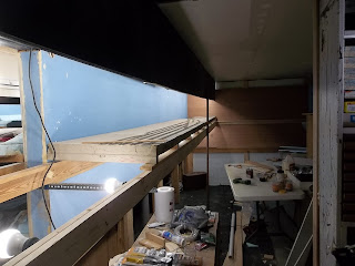
The helix module will occupy a space 4 foot long, 4 foot wide and approximately 24 inches or more in height. The sheer size and weight of the module requires some modification of the WWSLs L-girder costruction techniques.

As seen in the lower photograph the major change is the absence of the horizontal 1"x3" as part of the lower L girder. A temporary 1"x3" was used to ensure level of the horizontal girder and the installation of the backdrop panels.

Next, the helix base was constructed. To minimize weight, I opted to use 1/2 inch plywood for the base. 1"x4" inch L-girders were constructed and installed around the outside edges of the plywood panel for strength. L-girders along two edges of the the panel were set in the traditional internal orientation, two L-girders along the other two edges were oriented outward. All 4 corners were reinforced with metal brackets.

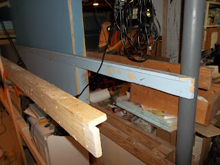
Heres a view of the reversed L-girders. In this case the horizontal L-girder members are 1"x2" dimentional lumber. They are oriented outward so that when the module is installed on the benchwork, the 1x2 horizontal edges hooks onto the benchwork holding it in place until a leg can be temporarily installed, the module leveled, and galanized screws inserted to lock the module onto the benchwork.


Having gotten the base installed with a temporary leg, I then cut the luan panels I plan to use for the helix roadbed to 48"x48" inches. I then temporarily installed them on the plywood base and aligned them to the base. I screwed them to the plywood base and then sanded the cut edge with a belt sander. 

The lower level has the helix foundation base for stability. The upper level needs a L girder for stability. I used a 2"x2" stud for the helix leg. I cut the corners of the luan panels and the 1/2 inch plywood panel, placed the leg inside the L-girder corner and screwed it into the L girders.


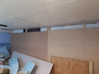
It is my plan to enclose the helix. The east side of the helix will be painted per the lower level sky color. The north side of the helix will be mostly enclosed as fascia and painted black. To make the backdrop and facia panels flush with the Lgirders at the leg, a 1"x3" and 1"x2" was attached as trim pieces. 


Now that the helix base is built and installed, I can finish the benchwork in the south east corner of the layout room and call benchwork construction over.

Sunday, May 22, 2022

Construction Section

On the right hand side of the blog I have created a section called Reference Pages. Each aspect of model railroading has a 'section' that consolidates general and WWSL specific model railroading information.

This month I have focused on formatting and consolidating Construction information. The index page is 3.0 Construction. The following topics have been identified and sorted. Information will be updated as I get it all together.

3.1 Construction Concepts
3.2 Layout Room Amenities
3.3 Benchwork


3.4 WWSL Stud Wall
3.5 WWSL L-Girder Framing
3.6 Backdrop
3.7 Valence / Fascia
3.8 Lights
3.9 Section / Module Design
3.10 Helix
3.11 Transfer Table
3.12 Car Card Holders
3.13 Pen / Uncoupler Holders
3.14 Car Drawers
3.15 Under Deck Skirting


Benchwork Specifics
3.3.1 Open grid benchwork
3.3.2 L-Girder benchwork
3.3.3 Shelf benchwork
3.3.4 Multi-deck benchwork


Track Suppport Specifics
3.3.5 Flat top
3.3.6 Panel   
3.3.7 Cookie cutter
3.3.8 Spline


Wednesday, April 8, 2020

Benchwork 5

Benchwork construction continued along the east wall and the north side of the center peninsula in Zone 2 and 4.

Using standarized construction techniques found in Benchwork 4  I installed the the Upper and Lower Deck (rear) benchwork on the east wall.

I then constructed and installed the Upper and Lower Deck (rear) L-Girders on the peninsula. The backdrop only extends 16' with a 4-foot open end. For the rear L-Girders, I installed an 8' 1"x3" L-Girder, then a 4' 1"x3" L-Girder, and then installed a final 8' L-Girder cantilevered into the final open 4' area. This 8' L-Girder was made from a 1"x4" for improved stability when cantilevered.


The Upper Deck Front L-Girder was constructed of two 1"x4" L-Girders 10-foot long, installed 24-inches from the backdrop and attached to the valance with the 19-gauge dark annealed steel wire.


The lower Deck Front L-Girders were constructed and installed using the same techniques. The cantilevered L-Girder was leveled and secured to a leg cut to size.


The Upper and Lower Deck Front L-Girder benchwork on the east wall was measured and cut to fit between the north and center peninsula benchwork.


I also installed Lower Deck String 1 along the north and east wall and parts of the Upper and Lower Deck Strings 1 and 2 to the upper cantilevered section.


Sunday, October 11, 2020

Benchwork 8

The last major section of benchwork to be installed was along the south wall. I knew this was going to be something out of the ordinary because this was new construction per se. All previous benchwork came from WWSL version 2 and was pretty simple to build and install. This section was unique in that it was the location of the helix, and helix construction causes all sorts of benchwork issues. 

Undaunted I forged ahead. The valence along the south wall in zone 3 was built. I initially planned to continue the benchwork at 24 inches in depth leaving an 8 inch gap between the layout and the south wall. Sanity quickly over-welmed me as i realized two things: 1)  an 8 inch gap either requires another stud wall, or 2) I would have to divide two 8 foot modules and insert a special 8 inch module piece somewhere along a straight track section so if i ever moved, i would not have to rebuild multiple curved track. Neither solution was appealing to me. 
 
I came to the conclusion that I could use that 8 inches to solve some layout issues I had with the Lumber Camp and the NP interchange yard. (More of that later in the layout planning blog). The four modules on the south wall would be 32 inches in depth rather than 24 inches. Up went the standard compressed stud wall, the lower L-Girder, and the backdrop panels. 


At this point I need to reverse my normal installation practice. Previously the upper deck was installed first and the lower deck last for ease of installation. This time around the helix base has to be built and installed, then the lower deck built and installed. The upper deck was then gets measured and installed temporarily - knowing final installation was dependent on the location of the helix exit point. 
 
Helix building is a whole new subject that i will get to shortly. .


Sunday, May 31, 2020

Resources 3 - Money

In Layout Design Process 4 - Railroad Modeling I identified that the layout design process can be broken down into three primary functional areas: Concept, Structure and Layout Detail.

Structure. Structure identifies the parameters within which the layout must be designed. It is broken down into two main elements: 3) Resources Available to build the railroad, and 4) Layout Planning.

Under the element Resources Available, the following areas are considered: 3) Money.

Money


We generally don't talk about the cost of a layout. Our first layouts are often based on the toy train set we got as a birthday or christmas present. Plywood and 1xs dont cost much and the cost isn't calculated. As we get older we have three ways to approach budgeting:

  1. Freelance work (pay as we go) on your railroad.
  2. A set budget of what you want to spend for the railroad.
  3. No set budget and willing to pay for what you want.

Material and component selection. 


I believe that we all have at one time or another build a layout based on our financial capability at the moment. Early layouts no dobut featured sub-par materials and locomotives and rolling stock brands that looked great but ran poorly. As our financial capbility improved (and the model railroad industry improved quality) our follow-on layouts were upgraded and improved upon. A layout featuring high quality track, components, and rolling stock is a pure joy to run.

Friends over the years have asked me how much my layout cost. Frankly I hadnt kept up with the costs, 1) because it was a hobby, and 2) some stuff i bought retail, some I bought at train shows at discount, some was donated, and all of it was obtained over years in the hobby. I still have my original train set i got as a gift from my father .... its been recycled over the numerous layouts I have constructed over time.

For those who are entering the hobby for the first time, there is a cost. Model Railroader magazine has for years published entry level model railroad plans. The last entry level plan I read about was a 4x8 foot layout with DC toy train locomotive and rolling stock and basic sectional track and turnouts and a modest number of structures. The publishers indicated the price at approximately $500.00.

Custom model builders are out there willing to design and build a model railroad layout for those who dont want the thrill of benchwork construction, tracklaying, electrical wiring and scenery and structure building. One builder ranks his services as B level (basic benchwork, roadbed and track) or . Prices start at about $70 - $95 per square foot for a B Level HO or O scale layout. This would include . N scale layouts are about 50%--75% higher on a square foot basis. A or AA level quality will add 15% and 35% respectively.

The basic scenery portion of a layout (rolling hills or flat areas with grasses, dirt and gravel coverage) will add from $25 - $50 per square foot over the base price depending upon the amount of contouring. Extensive rock outcroppings or cliffs/canyons will be $55 - $100 per square foot or more additional depending on the extent of vertical coverage and level of detailing. Streams, rivers and lakes will add $35 - $90 per square foot over the base price depending upon the level of detail. Urban areas with their high concentration of structures, roads, streets, figures and details will add $55 - $120 or more per square foot to the base price depending upon the structure types and density.

As you can see, the custom costs can be astronomical. If you're doing it yourself (DIY), you will not be paying the hourly rate for the custom builder's time and effort. Those who DIY often estimate their efforts at $60 - 100 per square foot depending on the size and quality/quantity of their layout and equipment. 

WWSL costs 

 
As I have indicated earlier, the WWSL is version 3, and I have recycled alot of the benchwork, modules, trackwork, locomotives and rolling stock over the years. For this blog, I have gone back and calculated the costs of room preparation, benchwork, right of way, trackwork, locomotives and rolling stock assuming 2020 prices. Fortunately 20 years of model railroading brings with it lower entry costs and long term savings, so the pricing you see below is NOT what I've paid so far. It does however give you an indicator of current costs (or replacement costs for insurance purposes).


Room Preparation


Benchwork


Module


Trackwork


Locomotives and Rolling Stock


Sunday, February 14, 2021

Modular vs Sectional Design

Modeling Information

There are two types of layouts, movable and immovable. Having been in the military for 14 years and moved some 8 times in those 14 years, I opted for a movable type of layout. I've moved it three times in the next 20 years as a civilian. 

There are two types of movable layouts: modular and sectional.

Modular Type A. By definition,  a module is a section of benchwork and roadbed that is built to  common standard determined by the organization establishing the standard. Modules fit together with standard track connections at the ends, but builders can construct any kind of scene on a given module. - as long as one module fits against another module railwise. Modelers are generally confined to fixed-length modules of 4, 6, or 8 feet long.

Ntrak is one of the modeling organizations that has created a commond standard and other modeling groups have developed standards of their own. Those layouts you see at train shows and flea markets are modular type A layouts.

Modular Type B. Another group that does modular but differently is Fre-mo. Free-mo was developed with the idea that allows the modeler’s creativity to shine through their modules.  The Free-mo standard focuses mainly on the module end plates. The Free-mo mainline is centered on a two foot end so modules can be inverted 180 degrees and still mate up to the adjacent module without modification to wiring or track. This allows modeling of prototype track plans and operations in a modular environment. The length and track configuration of a Free-mo module or module set is up to the modeler as long as the module end plate standard is followed. .

Sectional. Sectional design assumes that the layout is going to be moved at some point. Unlike modules, the sectional layout does not follow any standard track pattern because the pieces need to fit together only one way. The scenery can maintain continuity from section to section following the theme of your railroad.

Benchwork is the same, the only difference is the connection points are designed with a move in mind. Assuming you don’t have to take your show on the road very often, you don’t even have to leave breaks in the track and scenery at section joints. When it’s time to move, simply cut the rails and slice through the terrain. As long as you have some extra track and scenery materials on hand, you’ll be able to “heal” the scars at the section joints

Dominos. David Barrow devised a sectional construction system using standardized rectangular layout segments (think table layout that disassembles). He likes to lay out track plans by fitting these sections together end to end and forming 90-degree corners, so the comparison to the game of dominoes was obvious. He’s  described his domino method in both Model Railroader and Model Railroad Planning articles. The illustration shows the basic form of domino layout sections.

The WWSL

WWSL ver. 2.0 was several concepts wrapped up in one. I wanted modular construction that would be easy to move . I was taken with the idea presented by David Barrows about 'domino's. His choices for his layout was:

  • Segmental benchwork construction.
  • Minimalist design aesthetics rather than a realistic scenicked railroad.
  • Wide aisles.
  • Finished open room with carpeted floor.
  • Off-the-shelf unpainted code 100 flex track and no. 6 turnouts operatied by manual ground throws to minimize wiring and complexity.

This made a lot of sense to me - after all all my layouts to date had essentially been minimalist designs rather than realistic scenicked railroads. Heck, I hadn't even painted the plywood green!

This minimalist idea was followed by Tony Koesters Layout Design Elements That allowed me the opportunity to develop a model railroad focused on operations with an ability to change the layout based on my change of operational preferences. I always enjoyed switching, and car movement, mainline operations as shown in the model railroading magazines of the time less so. I did enjoy the freedom to build a multi-track coal mine with empty and load yards, and then months later change those LDEs to reflect a grain elevator and its similar but also unique requirements. Wetting down and removing the white glue'd down flex track and re-configuring the industrial spurs was a way of continuing the hobby as I enjoyed it. 


The WWSL vers. 2.0 domino. While David Barrow's dominos used plywood as its subroadbed/roadbed, I knew at some point I would decide to do a WWSL vers 2.0 which would entail scenery, etc.  Mounting a plywood base directly on the bench work gives you ZERO opportunity to work in any downward verticle scenery. I saw styrofoam and the 2" x 2s as a way of allowing the vers 2.0 the option of having some features such as roadbed slopes, small streams, culverts, bridges, etc. 

The requirements of the military move didn't support the idea of L-girder benchwork, so my modules were constructed so that when it came time to move all i needed to do was disassemble them into the core 2 foot x 8 foot sections and then surround them with 1/4 inch plywood to avoid the inevitable move damage.

The section was essentially a two inch piece of styrofoam glued to a 1/8th inch of masonite with wood  glue. A twenty four inch 2" x 2" piece of lumber was screwed and glued into the masonite panel and was then screwed onto an L-girder made up of a 1"x 2" and 1" x 4" lumber. 2" x 2" legs were bolted to the L-girder ala Lynn Wescott.

In this case, the styrofoam, the masonite, the 2" x 2"s and the 1"x3" gives approximately 4 inches of downward dropping scenery potential. 

The WWSL vers.3.0

The WWSL vers. 2.0 was single decked for a number of years. I found that the second level was difficult if not impossible to install with the L-girder in place. When I started the benchwork for WWSL vers 3.0 I removed the Lgirders and installed a horizontal 1"x3" in its place - to add vertical stiffening to the section. This is what the vers 3 module looks like. 

I'm recycling 16 WWSL 2.0 sections to the new version. I've found those sections much easier to built, carry and install on the layout.  

See 3.9 Module / Section Construction for construction details.

Wednesday, May 20, 2020

Benchwork 7

The valence along the center peninsula was built and installed. The party light string was continued from valence level in Zone 2 around the end of the peninsula and down to the end wall.

The upper benchwork frame was constructed and installed. The light string was continued from zone 2 around the end of the peninsula and down to the end wall.


I then built the peninsula end valence. An interesting measure twice, cut once exercise that I'll discuss next week in greater detail.


The lower benchwork frame was constructed and installed. I then moved the four modules from storage onto the benchwork.


The good news is that this construction frenzy completes the rebuilding of the existing version 2 layout footprint and completes STG #1:  I wanted the first half of the layout room constructed, utilizing the existing WWSL 2.0 bench work installed within 3 to 6 months.


Sunday, September 27, 2020

Layout Details - Construction Overview

Layout Details. Layout details identifies the specifics xxx. It is broken down into two main elements: 5) track planning and 6) construction. Construction consists of four subsets:

a. Human Factors. This basically answers what you want your layout room to be able to do when you are finished.

b. Lighting and Electrical. This section identifies the general and layout specific needs in terms of lighting and electrical.

c. Room Preparation. This identifies the deconstruction and construction to be done's (TBD) that need to be done.

d. Benchwork. Finally! When everything else is done, this section identifies what type of benchwork needs to be constructed.
 
Human Factor. Here are the areas for consideration. 
  • Access to Utilities. Access to set tub, washer and dryer connections. Access to electrical panel, basement drains, and water meter. Access to furnace and water heater. Here were my utility locations. 
  • Crew Lounge. A crew lounge was a luxury I wanted, even though I am a lone wolf modeler. I anticipate recruiting a crew and opening the layout to tours at some point of  time. Combining the Crew Lounge and the Utilities area made alot of sense!
  • Good Storage. I wanted a lot of general storage under the layout.

  • Large Aisles. I'm NOT a fan of small aisles. Been there done that. I like large open areas to work and move through.
  • Clean area. Drywall ceiling, painted walls, and indoor outdoor carpeting.
Lighting and Electrical
 
  • Good Lighting. The original basement had 4 100 watt light bulbs. I wanted 4 total general  lighting zones in the basement, and and an outlet for each of my layout lighting zones. I needed to add nine light switches to control all the lighting zones.
  •  
  • Improved Electrical. There were only two wall outlets in the original basement configuration. I wanted at least two outlet boxes on each wall. I added 6 circuit breakers to my circuit breaker box in anticipation of layout lighting and power needs. 
Room Preparation. 

Deconstruction of the layout space. This is what I had when I went downstairs to the future layout room: Layout Room (Before)

Constructing the layout space.  There is a theory of construction. Of course I didn't follow the construction concepts below for a variety of reasons, including stupidity. If you want to see what not to do read my construction articles beginning here Room Preparation.

  • Empty the space. Working around storage piles, etc is counter-productive time wise.
  • Start at the top and work your way down. This means install all the electrical and lighting in the ceiling, add whatever cable or plumbing requirements, etc.
  • Drywall the ceiling. I found based on my existing basement height, and my desire for valences, that a drop ceiling would not be ideal. All major plumbing raceways are open to repair - the raceways are covered with luan plywood for ascetics. 
  • Work from the outside of the space to the inside.  Fill all cracks in the wall as required. Paint the concrete walls with waterproofing paint.
  • Build interior stud walls (outside walls first, then interior walls).
  • Add electrical and cable wall outlets as required.
  • Drywall as desired.
  • Carpet the floor.

Benchwork
 
WWSL vers.3.0 is salvaged from vers 2.0. I will be using a stud wall, L-Girder frame work and panel type benchwork. See 3.0 Construction for specific details

Sunday, December 6, 2020

Benchwork 10

 Benchwork construction is just about over and I'm glad it's coming to an end. 

Once the helix base was roughed in and emplaced, final benchwork can be completed. 

I installed the south wall upper level horizontal L-Girder. I then installed the east wall upper level horizontal L-girder - completing the upper level benchwork.


I then installed the lower level south wall L-Girder. Notice that I simultaneously installed the east wall L-girder. I had to do this to ensure that the east wall modules were correctly installed at the 8 foot length and whatever excess length of the layout room was reflected in the width of the south wall modules. I anticipated a 32 inch width of the south wall modules. The reality was 33 inches and I'm fine with that.


Not photographed but installed was a lower level leg installed along the south wall to hold up the lower module.


Sunday, May 17, 2020

Resources 1 - Time / Energy / Commitment

In Layout Design Process 4 - Railroad Modeling I identified that the layout design process can be broken down into three primary functional areas: Concept, Structure and Layout Detail.

Structure. Structure identifies the parameters within which the layout must be designed. It is broken down into two main elements: 3) resources available, and 4) layout planning to build the railroad. At the ed of the structure phase you should have identified the scale and size of your layout and a series of 'given and druthers' you wish to achieve in the track planning process. 

Under the element Resources Available, the following areas are considered:

  1. Time / Energy / Commitment
  2. Skills/Experience
  3. Money
  4. Space

Time / Energy / Commitment


Lance Mindheim, in his layout design blog, https://www.shelflayouts.com suggests that rather than let available space drive the planning process, the modeler should let available time drive the design. Lance believes that having time for layout construction may be the biggest factor when youre deciding how large a layout to tackle. Those with limited time due to pressing job responsibilities and competing interests will likely find that trying to build a several hundred square foot layout is ill advised.  Lance posits two specific questions:

    1) How much time does the modeler have to work on the layout?

    2) How long will the modeler have the layout?

In The Railroad Model Journey (http://modelingthewwsl.blogspot.com/2019/12/the-railroad-modeling-journey.html) I stated that I had a number of model railroad layouts in various sizes and degrees of completeness over the years. Some were incomplete by design, others went incomplete due to fatherhood and job responsibilities.

Rarely in the model railroad press is there mention of the time it takes to construct a model railroad. In the Model Railroad Planning 2004, Paul Dolkos wrote an article "How big should your layout be?" He discusses time, scope, availability of skilled help, money and maintenance. Paul introduces an 18' x 21- foot layout that Mat Thompson was constructing. Mat estimated that it would take 3400 hours to complete the layout. Those hours were based on: 

  • Benchwork  - 300 square feet -  100 hours
  • Track  -  600 feet  - 1 hour/foot - 600 hours 
  • Turnouts -  50 turnouts and switch machines - 3  hours/turnout - 150 hours
  • Scenery -  300 square feet  - 2 hours/square feet -  600 hours
  • Structures - 10 large building - 100 hrs each - 15 medium buildings 50 hrs each - 15 small buildings 20 hours each - 2,050 hours
  •  
Imagine the estimated hours for another layout Paul Dolkos highlights - J.D.Smith's Southern Rwy Rats Hole Division - 1900 feet of track, 203 turnouts. Using the Thompson baseline, J.D. Smith's estimate would be ~5400 hours absent scenery and structures.

The WWSL


Now that my family is grown up and on their own, and I'm semi-retired, its time to commit to  to railroad modeling. No more PTA, scouts, car pooling, overtime at the office, and the myriad of commitments that comes with family. I will have the time to build out the layout. For my last layout I'm assuming it will have a lifespan of 8-10 years. That number isn’t something I pulled out of thin air. I'm 64 right now. Based on a variety of factors, I anticipate 8-10 years of productive retirement life. Im in my retirement location.  I anticipate the heavy lifting of layout construction (things like the benchwork, track, wiring) will be completed in 2 years.Everything else is 'gravy'!

I've estimated that i have about an hour a day and 6 hours a weekend for layout construction. I’ve found that plugging away on the layout a little bit every day is a good way to make fast progress. On weekends I’m able to get 2-3 hours done at one stretch, but during the week even half an hour before I head for bed speeds things along.

As I have already planned and constructed parts of the WWSL in previous configurations, I know that I have approximately 400 square feet of benchwork (150 hours),  200 feet of track (200 hours), and about 50 turnouts (100 hours), scenery (400 hours) for a total estimate of 850 hours less structures.

If you recall in my Long Range Goal's -  LTG #5: I want the layout to be completed to general standards within 3 years, and enjoyable for a total of 8 to 10 years. I want the layout to be affordable, utilizing my existing modules, locomotives and rolling stock whenever possible. I have a number of modules and backdrops already constructed and in storage. If you have been following my construction pages you will see that I have completed approximately 75 percent of the benchwork through judicious recycling and new construction and materials as needed.


Sunday, November 8, 2020

Valence 5

This last work session was focused on finishing up bits and pieces of valence and ceiling projects. 

  • Drywall panels that i had delayed putting up were installed in zone 1. 
 
  •  Spackling was done in zone 1, 2 and 3 finishing up ceiling work that had been done in bits and pieces. 
  • The valence extending over the helix was built and installed.


  •  Party light string was installed on the upper valence. 
  • The upper outer l-girder was installed.
 
 
Next week I have to build the helix benchwork so i can finish the upper and lower deck benchwork and call overall benchwork construction done !


Wednesday, February 19, 2020

Benchwork 2

There is an old carpenter axiom "measure twice, cut once". There's also an idiom "one step forward, two steps back". So it was in my initial wall construction.

I got the first two walls up using the compression-stud benchwork in my last post (http://modelingthewwsl.blogspot.com/2019/02/benchwork-1.html). I then went out and rented a laser leveler to locate the zero elevation line and mark the studs so I could then install the lrear lower level L-girder and the luan backdrops. I was able to quickly do two wall, the leftmost 30-foot wall and one 12-foot wall.

When i installed the 4'x8' foot luan backdrops i noticed they didn't line up vertically as well as I expected. I pulled the 4-foot level out and ran it along the top of the backdrops and was surprised to see that they weren't level - the bubble wasn't close to center in the tube.

I went to the rental company and re-rented the laser leveler. This time I went to the web site and downloaded the instruction manual and read it. Imagine my surprise when I read on the last page that the laser was accurate to 5/8 inch at 50-feet. Review of other brands of laser levelers of varying prices revealed accuracies of 1/8" to 1/4" per 30-feet.

I discussed this with a contractor friend of mine who confirmed that level varies by price, and by the care of the leveler by the owner. His leveler was accurate to 1/16th inch in 100 feet, and he said it was well worth the cost for his construction needs. He expressed surprise that I had gone to the expense of a laser leveler for such a small area. He reminded me that a low tech high accuracy tool in my garage would do just as well - a chalk line and a torpedo level!

Being the friend he is, he brought his expensive laser leveler over and shot the new zero elevation line. Sure enough my 30-foot wall was 1/2 inch off - my chalk line and torpedo level 1/16th off.

I can accept a deviation of 1/16th inch. So back to deconstruction and reconstruction.


Sunday, July 5, 2020

Layout Planning 5 - People oriented Parameters

In Layout Design Process 4 - Railroad Modeling I identified that the layout design process can be broken down into three primary functional areas: Concept, Structure and Layout Detail.

Structure. Structure identifies the parameters within which the layout must be designed. It is broken down into two main elements: 3) layout planning, and 4) resources available to build the railroad.

Under the element Layout Planning, the following areas are considered: 5) People oriented Parameters.

History
  •  Create a history of the railroad and its industries based on and consistant with the actural history of the region and the existing industrial base of the period.
 Operations
  •  Uses one or more prototype railroads to establish a set of operational guidelines and then create a railroad within the chosen framework.
  • Layout design to achieve believable operation with plenty of action and suitably challenging.
  • The layout to accommodate the owner and his interests and at least 4 operators for any public operating sessions.
  •  Design a walk around track plan so operators can follow their trains.
Construction
  • Construction, maintenance and operation of railroad to be within the capability of the owner.
  • L-girder benchwork. 1x3 and 1x4 L girders.
  • Benchwork based on WWSL vers 2  portable modules. Modules are connected to each other and the benchwork with alignment pins.
  • Recycle as much of the previous WWSL version 2 layout as possible. 
  • Railroad operating levels are between 38 and 58 inches above the floor allowing room for under layout storage and work space.

Control  
  • Walk around control of trains.
  • Manual control of switches whenever possible.
  • Train Order dispatching.  
  •  Use of railroad manuals etc
  • No signaling except at junctions with Class I or II railroads.

Human Factor 

  • Prepare the layout room for year round comfort and usability. Include a small crew lounge and work area.
  • Create an inviting space (I feel a layout should invite the visitor/operator into the layout space) 
  • Storage space under the layout. 

Wednesday, February 12, 2020

Benchwork 1

The WWSL v1.0 was conceived and constructed in 1987 while I was still in the military. Knowing that moving every couple of years was a reality, I decided that the railroad would be a sectional layout; each module would be no larger than two foot by eight foot. Since then I have successfully moved v1.0 and v2.0 four times.

Version 1.0 was a free standing (tabletop) layout. Version 2 was a two level shelf layout anchored to a dry walled stud wall. Version 3.0 is located in a basement with poured concrete walls. A traditional basement interior wall framing with drywall was possible but local building would have classified the work as a finished basement and significantly increase the taxes for the building. I chose instead to use an ingenious system developed by Malcolm Furlow and published in the January 1988 issue of Model Railroader. It's called compression-stud benchwork. Malcolm used 2x2 lumber with a T-nut and carriage bolt on one end and a small piece of thin plywood on the other. The entire assembly was cut to the height of the wall less a 1/2 inch or so, then tensioned between the floor and ceiling using the T-nut to provide a sturdy foundation for brackets, girders, and other shelves. 

I adapted the concept using 2"x2" lumber attached to the wood sill as the ceiling point, and 2"x4" and 2"x6" studs. I used 3/8" x 3" zinc screws in lieu of the T nut and carriage bolt, and used a 4-inch mending plate to attach to the 2"x2" top plate. 


Corners were created with one 2"x4" and one 2"x6". The 2"x4" was screwed on end to the face of the 2"x6" allowing 3 inches of usable facing on either side for attaching the backdrop (I use 4 foot by eight foot luan plywood). A 2"x4" studs is placed at the four-foot mark, a 2"x6" at the 8-foot mark, then repeated along the entire wall. The compression stud is leveled vertically and horizontally.

I use L-girders as the horizontal elements for my benchwork. As I am building a two level layout, my lower L-girder is built with a 1"x3" and a 1"x4". The upper level L-girder is built with two 1"x3"s. I got excited about getting to this level of construction and before i knew it I had a 30-foot wall constructed and the luan backdrop installed.


Layout height considerations, backdrop painting etc will be discussed in later posts.

References:

Model Railroader, January 1988, Carbondale Central, Malcolm Furlow.

Great Model Railroads, 2015, Less is More, James McNab.

Wednesday, March 18, 2020

Lighting Concept

 This week we are going to look at the lighting plan for the layout room.

There are as many strategies for layout lighting as there are layouts and you will find owner strategies in various model railroading magazines and internet sites. John Armstrong, in his book Creatove Model Railroad Design, has a 7 page discussion of layout lighting that is worth reading, particularly his section on layout lighting criteria. I will briefly note John's  6 criteria for your further researching.

  1. It should be safe.
  2. It should be easy to install and operate.
  3. It should be easy to maintain.
  4. It should be unobtrusive.
  5. It should be simulate sunlight.
  6. It should not generate unnatural effects.

Where John started the layout lighting discussion, i refer you to Lighting Your Layout, a clinic developed by Max Maginness . Max continues John's discussion with his forum on Layout presentation through general lighting and identifies his solutions to the layout lighting.

Ceiling Lighting


The WWSL's basement is divided into 4 zones. Each zone is controlled by a standard wall switch. One switch is located at the top of the stairs and controls the workbench area. The other three switches are located at the bottom of the stairs and controls the other three (layout specific) areas. Each area is approximately 12' x 12' and has a minimum two 65w can lights. These lights are connected to one 20 Amp circuit in the load center.

Layout Lighting


The layout is divided into 6 zones approximately 40 foot long; three zones on the upper deck, three on the lower deck. Each zone is controlled by an outlet that is in turn controlled by a standard wall switch located at the bottom of the stairs.

WWSL version 2.0 was lit with 8' long fluorescent tubes. Installation was difficult. Each tombstone was secured to the valence (upper level) or under the L-girder benchwork (lower level). The ballast was centrally located on each valence/L-girder and then individually wired with both 12V and 120V. Installation of each one took about an hour. I definitely didn't want to do that again.

WWSL ver 3.0 is going to be lit with party lights. I learned of this technique from reading an excellent blog at http://www.lkorailroad.com. Party lights are a commercial grade string of lights designed for outdoor use. They come in a variety of lengths and styles. They are UL approved. I purchased five 48 ft Medium Base String Lights - Black from https://www.partylights.com/48-Medium-Base-Stringer-Black. There are 24 sockets on 24 inch centers on each string.

My lighting strategy is to secure the Light String to the Valence and the Upper Deck Front L-Girder.

It will be easy to install and operate. It will be easy to maintain. It will be unobtrusive.Here is a picture of one of the sockets. It has 4 convenient tabs that can be used to secure it to the valence and L-girder benchwork.


The light string was easily attached to the valence and L-girder benchwork. For illuminating the upper deck I screwed a 1" x 3" parallel and above the bottom valence 1" x 3" at three points (ends and center). From the normal viewing angle, the lights cannot be seen. For illuminating the lower deck I installed an additional 1" x 4" along the upper level L-girder (strengthening the upper L-girder), again attaching it to the L-Girder at three points. If I should ever move again, the removal of three screws from each light bar will allow for easy removal and transport without disassembling each socket or run. The lighting string electrical cable will keep each zones sockets and bulbs together for easy transport and installation.

On all lighting bars I marked 4 socket locations at 1', 3', 5' and 7'. Each light string socket was screwed to the light bar with two 3/4 inch lath screws. The end of the light string was plugged into an outlet controlled by a wall switch at the logical end of the run. When it reached the end of the run and additional lights were still available, the string was cut at the end and capped The unused sockets at the ends were recycled into Upper Deck 3 and Lower Deck 4 socket strings.

Simulating Sunlight


Layout lighting becomes real confusing if you intend to photograph your layout. Different lightbulbs require different filters on the cameras, different wattages for 'bright enough' coverage, and lets not get into side and backlighting of the layout.

My intent is to have sufficient daylight lighting for operations. After review of the available lighting options, I opted for LED lighting, for long term economy and ease of maintenance. When looking at specific light bulb specifications it began to get confusing. Foot candles vs lumens, tungstun vs halogen vs LEDs etc got me totally confused for a while. The government helped me out quite a bit by mandating the change from incandescent lighting to LED.

Next was to find appropriate bulbs. This is where David Stewart was helpful. His blog page, Layout presentation through general lighting, descibes the modeling aspects of lighting based on color temperature and color rendering.

Color temperature describes the general color fundament of the light emitted by the bulb in degrees Kelvin. He notes that two color temperatures can be appropriate for layout lighting:
  • 5000K—Mix of sun and clear blue sky, also the most common daylight fluorescent color.
  • 6500K—Color of daylight in shade with a clear sky with high humidity.
As I am modeling the Pacific Northwest, in particular the Grays Harbor area, its a mix of sun and clear blue sky with high humidity (being close to the Pacific Ocean). Going to the local hardware store i found 5000k daylight 40 watt and 60 watt equivalent LEDs, (hereafter categorized by the actual wattage 6w and 9w). OK, forget about the high humidy !

Next is color rendering. The color rendering index number gives us an idea of how accurate colors will appear when viewed under that light, relative to their appearance in full sunlight. For photographic purposes a CRI above 85 is preferred to avoid colors looking dull and muted, particularly reds and oranges. I'm not particularly photographically inclined, so CRI isnt a big item on my given and druthers list. If i do become so inclined i will find appropriate high CRI rated bulbs and replace existing bulbs for photographic purposes only.

Of more significant concern is the bulb wattage. First, the distance from rail head to lamp is roughly 24″ on the upper deck but only 16″ on the lower. 9 watt LEDs produce 800 lumens, 6 watt LEDS produce 450 lumens. The upper deck lights must illuminate a 24 inch backdrop, the lower deck lights only a 16 inch backdrop. The upper modules are painted white on the underside thus increasing light reflectiveness on the lower level. Max's clinic suggests 100 foot candles per square foot for a sceniced layout. Not quite sure how the different distances will influence foot candles, etc., I'm going to initially use 9watt 800 lumen bulbs on the Upper Deck and the 6 watt 450 lumen bulbs on the Lower Deck.

Energy Requirements


This is the present requirements for layout lighting as expressed by location.

Lighting                         Type Output Wattage Input Amperage
Upper Deck String 1      LED 20 x 9W                 3.6 @ 115V
Upper Deck String 3      LED 20 x 9W                 3.6 @ 115V
Upper Deck String 5      LED 20 x 9W                 3.6 @ 115V
Lower Deck String 2 LED 20 x 6W                  2.4 @ 115V
Lower Deck String 4 LED 20 x 6W                  2.4 @ 115V
Lower Deck String 6 LED 20 x 6W                  2.4 @ 115V

The total amperage for the entire arrangement (ceilig and layout) is 21.9 amps. I am installing two 20A circuits in the load center. 


Reference:

John Armstrong, Creative Model Railroad Design. 1978, 1980, 1990.

Max Maginness Lighting Your Layout ,

Sunday, May 24, 2020

Resources 2 - Skills / Experience

In Layout Design Process 4 - Railroad Modeling I identified that the layout design process can be broken down into three primary functional areas: Concept, Structure and Layout Detail.

Structure identifies the parameters within which the layout must be designed. It is broken down into two main elements: 3) resources available to build the railroad, and 4) layout planning.

Under the element Resources Available, the following areas are considered: 2) Skills/Experience.

Lance M in his blog lancemindheim.com. discusses the skills and experience factors in layout design and construction. His bottom line observation is:'If you haven’t built a complex layout before maybe you do a flatter, simpler one first.

Experience


Let's talk Experience first. Have you built any layouts before?

The modeling press has identified that a model railroader typically enter the hobby at two points in their lives, either during the teen years or at retirement. Those coming into model railroading later in the life do so with many more resources than their teen counterparts. On the surface that can seem like a good thing but, more often than not, it can be a case of the proverbial “having enough rope to hang yourself”. The sixty or seventy something retiree often has ample space and funds to commit to grandiose plans that he has yet to acquire the skills to execute. The teen has neither ample space or funds, nor has the skills to execute.

Lance suggests that the entry level modeler should warm up to the hobby by building smaller practice layouts first. Model Railroader magazine has always catered its articles on the beginner in the hobby. They recognize that early success and momentum is crucial when it comes to building passion for the hobby. On the flip side, hard to build elements can create construction quagmires that bog a persondown as they face one construction challenge after another. The key to success is to keep the first effort simple, something that falls together easily. The acronym KISS - Keep It Simple Stupid - is one of two signs currently occupying my layout room. (The other sign is - Think like a Short Line.)

As i indicated in my blog Layout Desig Process - Train Set, there are a number of layout design planning magazines and books out there that have beginner layouts already designed. I will admit that there were a couple of oval, figure -eight, and 'spaghetti-like' layout plans in my early years. I will also admit that they were short duration layouts - a train going round and round and round just got boring pretty quick and I 'graduated' to shelf layouts with less round and round and more industrial switching activities.

Lance has designed and built 4 small layouts that certainly are a cut above the layout designs of the 70-s and 80's . You can find them here. Lance's suggestion for a beginner layout would be: two inch extruded foam sub-roadbed base, Atlas code 83 flex track for the straights, Atlas 24 inch sectional track for the curves, and Atlas number six turnouts. I didn't have extruded foam available i my youth - plywood and homosote was subroadbed and roadbed standards at the time - but it makes sense today. 

It was an article in the 1995 Model Railroader by David Barrow that caught my eye and set me on the modular course that I have continued to use to this day, and it certainly supports Lance's thoughts of beginner layouts. He developed layout benchwork that was minimalist in nature, easily constructed (and deconstructed) and practical for the growth of the modeler as he obtained skills and experience.In articles written over the years he advocated recycling of materials, tacking down rather than gluing down track and turnouts, not using ballast at all, no scenery, etc. Not unlike model railroads constructed in the 40's 50's and 60's.

Skills 

 My dad once told me that model railroading was like the skill trades - first you are an apprentice, then a journeyman and then if you choose to progress - a master in the field. And he was right. Model Railroading is a hobby that offers alot of modeling opportunities for all levels of expertise. Benchwork starts with a saw, a drill, a screwdriver and a level, progresses to Lgirder and then open frame. Trackwork starts with a compass, a ruler, tack hammer or glue dispenser putting down sectional track and turnouts, followed by flex track and improved performance turnouts to handlaid track and turnouts. Locomotives start with ready to run (RTR) models to kitbatching and then scratchbuilding Scenery starts with a flat surface painted with browns or greens and progresses to wire or cardboard mesh and plaster, and ends with plaster rock castings, sculptimld and static grass and hand made trees in a variety of techniques. As a modeler you choose the level of interest you wish to pursue.

In LTG #4: I said i wanted to improve my modeling skill sets in the areas of scenery, electrical, locomotive and rolling stock kitbatching, and structure building. I'm a journeyman in the benchwork trackwork and electrical aspects of the hobby and an apprentice in everything else. I'm going to use the National Model Railroad Association Model Railroading Achievement program to advance my apprentice skills and hone my journeyman skills to the master level. I look forward to kitbatching and scratchbuilding prototype locomotives, rolling stock and structures appropriate to my railroad modeling Scenery-wise im not as accuracy focused - grass is grass, hills are hills, trees are trees, and if i can generally model a scene so it looks similar to the prototype photo I have of my area of interest i will be happy.

If youre a beginner, the Golden Spike Award is a good start. I will use the NMRA Achievement Program as a guide to my skill progression. Perhaps I'll make it to Master Model Railroader - you never can tell !

Sunday, June 6, 2021

Layout Design - 8 - Technical Specifications

Prototype Information

A railroad's operations is only as good as its personnel, operating plan, and its physical plant (right of way, yards, locomotive and rolling stock).

In order to ensure that each and every spect of operations is efficient, a series of documents outlining that departments operations is maintained. It is the same with the maintenance of way department.

The maintenance of way department is no exception. The department maintains a series of technical specifications on a wide variety of bridges, buildings, tools and track components used withing the railroad company system.

Fortunately there are two excellent sources of this information on the internet. 

  • Robert Schoenberg maintains a series of Pennsylvania Railroad system Standard MOW plans
  • Don Strack maintains a series of web pages that contains portions of the Union Pacific Common Standards book, a collection includes a large variety standards dating from 1904 to 1985.

Railroads standards were also on occasion mandated by law. I found (somewhere) a consolidated spreadsheet by state and track clearance requirements.

Check out your prototype railroad historical society or web site to see if there are standard plans applicable to your operations.

Modeling Information

The National Model Railroad Association (NMRA) has a series of Recommended Practices (RP) developed for satisfactory model operations based on existing model railroad equipment v. radii of curves and size of turnouts. Those figures, relationships or dimensions were established through actual tests and feel to be beneficial to model operation. Those recommended practices have been updated over the years, and the format I found the most interesting was RP-11, Curvature and Rolling Stock, Revised 1-90.


Andy Hamilton in the February 1991 National Model Railroad Bulletin suggested that 'Class' could be used in the hobby as a means of identifying the look and feel of the layout as it relates to operations, right of way construction and maintenance, locomotive, and rolling stock selection. 
 
Andy proposed that Prototype Class 1 operations would be expected to have broad radius curves and high speed (high number) turnouts, compared to prototype Class III operations (such as switching lines) that could be expected to have sharp radius curves and slow speed (low number turnouts).
 
The WWSL, the OPLC and the STC are Class III railroads. Using the RP format, recommendations for would identified under two Keys: 

Key F - MU and Light Electric
Key M - Standard Trunk Line
 
 
The WWSL


One day the WWSL will maintain a Common Standards book. In the meantime, you'll find those specific standards listed in the WWSL Right of Way Specifications and Modeling section of this web site. 

For general planning and construction purposes:

Human Factors. Here are the human factors used to develop the WWSL layout plan. 

Specification 

In inches

Aisle widths – normal

48

Aisle widths – constrained

30

Benchwork height – upper level

56

Benchwork height – lower level

34

Minimum track setback from Aisle

4

Minimum track setback from wall or backdrop

8

Maximum reach in distance from aisle to track

27

Bench work width for shelf style

24

Module standard width

24

Module standard length

96

Track Planning Standards.  The next step was to develop a set of standards for the trackwork. It would permit operations by virtually all HO scale equipment I would use in WWSL operations.

Specification                                     (In inches)

WWSL

OPLC

STC

Typical equipment length

40

 40

 40

Maximum equipment length

70 [1]

 50

 50

Track centers, double track, tangent

2

2

2

Track centers, tangent, Type 2 cantenary pole

3


Track centers, arrival departure track

3


Track centers, yard

2

2

2

Track centers, siding industrial track

3


Track centers, double track, minimum curve


Turnout number, single

5

6

5

Turnout number, crossover

6

8

6

Turnout number, ladder

5

6

5

Track curve, minimum radius, main line

26

26

26

Track center, double track, minimum radius


2

2

Maximum grade %

2.5


Vertical curve multiplier


Easement

28


Super-elevation

None

 None

 None

Minimum over/under track separation

3

 None

 None


Reference

NMRA recommended practices are:  


NMRA recommended practices are: RP-7 Track Centers and Obstacle Clearances RP-10 Trackwork - General RP-11 Curvature and Rolling Stock RP-12 Turnouts - General