Sunday, May 30, 2021

Layout Design - 7 - Track Plan Analysis (Part 2)

In Layout Design Process 4 - Railroad Modeling I identified that the layout design process can be broken down into three primary functional areas: Concept, Structure and Layout Detail.

Layout Detail. Layout Detail identifies the parameters within which the layout must be designed. It is broken down into two main elements: 5) Layout Design, and 6) Construction to build the railroad.
  
Under the element Layout Design, Track Plan Analysis (Part 1) considered the design against the layout given and druthers. In Track Plan Analysis (2) will be an analysis of the actual track plan as presently envisioned, and an analysis of operational trackage versus numbers of trains etc.
 
Modeling Information
 
That raised the question about car density on the layout. I found an article in Model Railroader by Roy F. Dohn that discussed a way to check the balance between main lines, yards, spurs and other trackage on a model layout. The purpose was to aid the railroad modeler in identifying the following data points:
  • Functional capacity of cars in yards and industry.
  • Functional capacity of the main line and passing tracks for movement of cars.
  •  

Data collection

The unit of measurement for this analysis is Car Capacity (CC) - the maximum number of 40' cars that can occupy each type of trackage. Actual footage doesn't work because car clearance requirements, etc. Each track is identified, measured and the data collected in spreadsheet format.

Those types of trackage to be measured were:

  • Running trackage (RT): Mainline and branchline trackage over which trains move to get to another part of the system.
  • Passing trackage (PT): Main line passing tracks, not within yard limits.
  • Maintenance and servicing trackage (MT): all trackage normally occupied by MOW cars, engine facilities, turntables, roundhouse, and similar tracks.
  • Storage trackage (ST): the total of Yard trackage (YT), Industrial trackage (IT) - basically all trackage on which equipment is stored when not running. 
  • Functional trackage (FT): trackage used for maneuvering between all the other elements - yard leads and ladders, passing and runaround tracks, inbound and outbound tracks within yard limits, and interchange tracks. 

Upon completion, the modeler has the maximum number of cars that can be physically held on the layout:  

(RTc - running trackage car capacity), 

(PTc - passing trackage car capacity),  

STCc - YTc and ITc), 

FTc


Number of cars moved (NCM) 

Cars in Service (CIS)


Data Analysis

With this information collected, the following information can be calculated: 

Storage Saturation (SS): percentage of 

Functional Saturation (FS) 

Funcgtional Main Line Saturation (FMLS):


Additional operational information is required for analysis. That information includes: 

  • Number of Cars in Service 
  • Number of Cars Moved 
  • InTransit Car Capacity Eastbound
  • InTransit Car Capacity Westbound

Once the data was entered into the database, car density was calculated and compared to a car density baseline suggested by the author. 

  • Functional Mainline Saturation (25-35%). 
  • Functional Track Saturation: (40-50%),
  • Storage Track Saturation: 33% (80-85%) ** assuming class 1 operations
  • Ideal Number of Cars is (30% of Storage tracks filled - Class 3)

The WWSL

An example

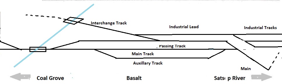
Let's use  Station 15 - Basalt for the example. Here is the Section diagram.


Measuring in 40' car length's for each track type we get the following data:


The entire WWSL layout. 

I did this for the entire WWSL layout. The results were:  

My operational information was included:

  • Number of Cars in Service  - 125
  • Number of Cars Moved - 80 (this included OPLC and STC operations)
  • InTransit Car Capacity Eastbound - 36 - (this included OPLC reload operations)
  • InTransit Car Capacity Westbound - 36 - (this included OPLC reload operations)

WWSL Analysis

 Based on the formulas in the spreadsheet, my Track Density for operations were:

  • Functional Mainline Saturation (25-35%) - 53% . 
    • InTransit Car Capacity Eastbound - (25-35%) -27% .
    • InTransit Car Capacity Westbound - (25-35%) - 24% .
  • Functional Track Saturation: (40-50%) - 25%
  • Storage Track Saturation: (80-85%) - 27%
  • Ideal Number of Cars: (30%) - 114
Analysis of the Analysis. I was surprised at how close my initial  layout planning ideas were confirmed by the data analysis.
  • Functional Mainline Saturation (25-35%) - 53% . The WWSL is a Class III railroad and has two additional Class III railroads it provides services to it. The WWSL main line is the means to getting to the customers on the line. 
  • InTransit Car Capacity Eastbound - (25-35%) -27%. This includes the OPLC reload (logging shuttle) operations, some of it on the WWSL main line. Totally consistant with Class III operations.
  • InTransit Car Capacity Westbound - (25-35%) - 24% . Again totally consistant with Class III operations. 
  • Storage Track Saturation - (80-85%) - 27%. Realizing the 80% is assuming class 1 operations, Class III operations would see primarily empty storage tracks as the norm.
  • Ideal Number of Cars -  (30%) - 114. I am using off-layout car storage for additional cars (for purposes of car interchange and car model type variety).
Reference
 
Roy Dohn, Layout plans by formula, Model Railroader, June 1968.

Sunday, May 16, 2021

Layout Design - 7 - Track Plan Analysis (Part 1)

In Layout Design Process 4 - Railroad Modeling I identified that the layout design process can be broken down into three primary functional areas: Concept, Structure and Layout Detail.

Layout Detail. Layout Detail identifies the parameters within which the layout must be designed. It is broken down into two main elements: 5) Layout Design, and 6) Construction to build the railroad.
  
Under the element Layout Design, the following area is considered: Track Plan Analysis.
 
The WWSL
 
At this point in time I have collected alot of information through the layout design process. Some of it is here and some is in the Station Plans.
 
Layout givens and druthers.
 
Concept. I am comfortable with the who what where and when aspects of the WWSL version 3.0 I particularly like the idea that i can model the three Class 1's and having the Olympic Peninsula Logging Company and the Saginaw Timber Company live and functioning is icing on the cake.


Operations. I am happy with the freight operations as envisioned. Passenger operations were considered primarily as a mechanism for building a timetable for Master Model Railroader certification. For daily operation, passenger operations is not a priority, it can be done and there are prototype examples for the trains. 
 
I believe that Demaine Yard is designed properly for a Division yard and sized appropriately for the amount of traffic going through the yard daily.

The layout design does address my interests in the natural resources industries. 'Keep it Simple Stupid' was the repeating mantra during the given and druthers stage and I think I've juggled those competing balls adequately. 

Single Track TT&TO operations can be easily implemented. The absence of a complicated signal system is a relief to me. 

An added bonus is the opportunity to model three distinct engine servicing facilities: electric, steam and diesel.


Construction. Fortunately for me I was able to recycle most of the WWSL version 2.0. Benchwork constuction was within my abilities, and new construction was about 25 percent of the layout room. Fourteen modules were reused, 12 modules were built new. 


Right of Way.
Double decking the layout was the way to go. I am comfortable with the two heights. The turnout count is high but reasonable given the degree of operating capability. Fine tuned commercial turnouts and flex track will speed up track laying. The track plan will have everything necessary for Master Model Railroader certification. 

The opportunity to build a myriad of bridges, culverts etc. is icing on the cake.
 

Scenery. A majority of the layout is flat, with scenic vignettes having most of the more 'difficult' scenery construction. It is however within my abilities. I'm looking forward to using the more modern scenic techniques employed since my construction of version 2.
 

Catenary/Signal. 
I've opted at this moment in time to model the catenary system minus the actual wire. Its not that im afraid of stringing wire, its the thought of trying to re-railing rolling stock or uncoupling them that gives me pause. Depending on my experience, I may rethink this decision after the majority of the layout is functional. 

Logically it makes sense that a short line would not have any signaling. Research indicates that the NP had an automated crossing with the Shafer Brothers rail crossing at Brady. That would entail semaphores for the NP branch line. I am thinking dwarf signals for the WWSL. The MILW/UP branch line had an automated crossing with the original Saginaw Timber Company. I am thinking dwarf signals for the WWSL there too. I'm looking at a couple of options that could be used to simulate those automated crossings.
 

 Locomotives and rolling stock. I'm looking forward to the opportunities to operate electric, steam and diesel units on the layout. Kitbatching the electric locomotives will be a skill upgrade for me. Steam locomotive operations is new and promising. I have in storage several 2-8-0's and smaller for operations. I've even got a 2-10-2 that could be used. I've got some history to justify it, but its but it's not going to be operational.
 
 
I'm pretty happy at the variety of rollling stock that can be used on the layout. I'm also looking forward to the opportunity to detail existing rolling stock and kitbatching existing cars that cannot be purchased.


Human Factors. I've always wanted a dedicated railroad layout space. Now I have it and it's met my expectations. Its fun to be down there (compared to other locations where I've had my layouts set up).  
 

Only one place has a aisle pinch point that doesn't meet the aisle parameter of a minimum 36-inch width to provide comfortable movement by crew - the right side of the layout where the workbench is located. Moving the center peninsula leftward was considered however the furnace air runs interfered with the possible construction of a stud wall and the two lally columns in the middle would interfere with personnel movement along the right center peninsula.  As it is a quick walk thru area with open space on either end for train control, the pinch point is considered a necessary evil. 
 
Having to duck under to get to the interior of the helix for track cleaning and maintenance is a necessary evil as well. Fortunately I'm still limber! 

Layout Design - 8 - Track Plan Analysis (Part 2) will be an analysis of the operational trackage versus numbers of trains, cars, etc. 


Sunday, May 2, 2021

Station 17 - Reload

WWSL 1st Subdivision         

Location.


Reload (Camp 11) is the newest of the Olympic Peninsula Logging Company's timber reload sites.

History. Truck logging in the Gray Harbor area began in the mid-1930's. I was unable to find any statistics on the Northern Gray Harbor timber area. In the North River Watershed (south of the Chehelis River), the Saginaw Timber Company started to build an extensive series of roads but was unable to capitalize on the work. Estimates were that 75 to 80% of logs were still moved by locomotive. 
 
By 1941, nearly 300 miles of forest road were created by bulldozer in the North River Watershed by the Clemons Logging Company. [1]
 
In the alternate history, the OPLC was moving to truck logging too. In 1936, 29 miles of truck roads was constructed on old RR grades, 7 miles was new construction. By 1950, 73 miles had been constructed with an additional 100 miles of protection road was maintained. The results were that a majority of steam locomotives supporting woods activities were retired and scrapped.                   

OPLC Camp 11 was built in 1950. Researching log reloading operations revealed most reloads consisted of a single track alongside a single (lane) logging road, with a dedicated locomotive placing/pulling logging cars (once a day).

Operations. I wanted this module to show a 1950's log reloading activity. Specifically I wanted to show:

  • Diesel logging trucks moving log loads from field collection points to the rail reload location. This would include the dirt road transfer point and a truck fuel point if possible.
  • An electrified crane reloader, in this case a crane reloader similar to one used by the Schafer Logging Company. It used a electric overhead crane with lifting bars. When weight on the bars is released, the heavy end tips up the bar to release the hook on the opposite end and the bar slides free from beneath the load. Log transfer is completed in a minute's time.
  • The OPLC will run a logging shuttle between the company sawmill complex and the reload site two or three times a day. The log shuttle will include a 2-8-0 steam locomotive, 6 log cars  and a caboose. Logging cars are a mix of skeleton cars and flat cars with side stakes. Additional cars that may be seen are water cars for fire fighting operations, tank cars (diesel) for truck refueling, and sand cars. See History of Flat Cars for additional information. 
Design. 
 
The right of way is owned and maintained by the OPLC and consists of a logging outpost camp, an overhead crane unloader and a refueling facility. As this is end of track, the OPLC will require an abbreviated steam locomotive service facility (water / sand) and a locomotive turning capability. A wye track would be the norm for this activity. 

Operationally the OPLC would segregate logs into sawlot and high value logs. Those high value logs would be primarily used for veneer and plywood. They would be sold to plants located in Aberdeen Hoquium or Tacoma. The WWSL will support this activity by maintaining a spur track for holding interchange-capable logging flat cars for OPLC usage.  

Track Diagram


Roadway.  
  • The logging car storage track is owned and maintained by the WWSL. The WWSL Main track ends at the far end of the turnout.
  • Main track is owned by the OPLC and is of recent construction.
  • Secondary track is a run around track connected to the Scale Track located on the Station 16 module. 
  • Auxillary tracks include the loading spur, supply track, wye. All non-main track is owned and maintained by OPLC and built to OPLC relaxed standards.
  • Not associated with the reload operation is a single track located at the rear of the module which is used by Station 16 - Coal Grove as the Empty Yard Lead. It is screened from the Reload module by a treeline. 
Scenery. 
  • Backdrop is sparse treeline.
  • Mid level space is broken terrain.
  • Front space is level terrain.
Structures. Structures located at this station will be:
  • Electric Powered Log Crane
  • Section house
  • MOW sheds (nice to have)
  • Water column
  • Sand House
  • Wye

Sunday, April 18, 2021

Station 16 - Coal Grove

Location.
WWSL 1st Subdivision
Coal Grove (CG) is the northernmost station on WWSL's 1st Subdivision.

History. See O.K. Coal Company.

The mine was originally a wood tipple. A fire in 1937 burned the tipple and it was replaced with a corrugated structure.

Operations. I wanted this module to show a 1950's coal loading activity. Specifically I wanted to show:
  • The mine head house, sorting tipple, loading conveyors and warehouse owned by the O.K. Coal Company.
  • Auxillary structures include a power house and transformer yard that supplies both the mine and the WWSL with power.
  • An empty yard, and a load yard.
  • A scale track.

The WWSL arrives at Coal Grove with empty hopper cars. The road locomotive places emptys, and pulls loads. Those loads are moved to the scale track for weighing. On completion, the train is reassembled and departs for Demaine Yard. Additionally, the WWSL may interchange with the OPLC. Empty log cars would be placed on the storage track on the Reload storage track, and loaded cars picked up on the scale track.

Design.

As I contemplated the design of Coal Grove I realized that prototype arrival (empty yard) and departure (load) yards were not consistant with class 3 operations. I chose to selectively compress arrival, departure and mine sidings with a simple yard operation. A diamond yard configuration was selected, the north ladder track would represent the empty yard lead, and empty yard, the south ladder track would represent the load yard. The module would be designate as a yard and operated under Rule 93. The main line would be the south yard lead supporting the load yard and the scale track. 

Track Diagram

Coal Grove is spread out over three modules. The Empty Yard Lead is located on the Reload Station module, the lead switch to the Load Yard Lead is located on a short (5 foot) module located between Coal Grove and Basalt.

Roadway.

  • Main track is owned by the WWSL and is built to relaxed standards.
  • Scale track is owned by the WWSL and is built to relaxed standards.
  • The empty and load yard leads are owned by the WWSL and is built to relaxed standards.
  • The two empty / load tracks and the supply track is owned and maintained by the OK Coal Company to relaxed yard standards. .
Scenery.
  • Background is Steep Terrain with Near Forest. 
  • Mid-level i s flat ground.
  • Near level is flat ground. 

Catenary/Signaling. Main track, scale track, and north and south yard ladders are under wire. Scale track has simple red (turnouts misalignment) / amber ( divergent track aligned) / green (scale track aligned) signal tied to turnouts.

Rolling Stock. O.K.Coal Company requires a variety of 50, 55, and 70 ton hopper cars (HM and HT) and gondola cars (GS). See History of Hopper Cars for additional information.

Structures. Structures located at this station will be:

  • Mine head (wood)
  • Mine tipple (corrugated)
  • Warehouse
  • Coal Yard
  • Power Plant
  • Transformer Yard
  • Mine entry  (nice to have)
  • Ventilation Shaft Building (nice to have)
  • Scale House
  • Scale
REFERENCES

Sunday, April 4, 2021

Station 15 - Basalt

Location.

WWSL 1st Subdivision
Basalt (BS) is the second northernmost station on WWSL's 1st Subdivision. located at Mile Post xx.

History. Originally named Camp 9, Basalt was originally the northernmost station on the OPLC logging railroad. Logging operations were terminated in 1930 due to the Great Depression. The location was then sold to the Basalt Sand and Gravel Company

Operations.

  • The WWSL arrives at Basalt with empty hopper cars. The road locomotive pulls loads and places empties. This could be either a local train or a unit train operation. Loads will be moved to Coal Grove andd weighed on the scale track. Any cars over tonnage will need to be set off to be reduced by plant staff. Any rejected cars for mechanical failure will be spotted at the Basalt RIP track. .
  • The plant has a locomotive crane that moves cars to and from the interchange with WWSL and within the plant. Track No.1 is the sand plant. Tracks No. 2 and 3 are the gravel plant.

Design.

I wanted to show on this module a medium sized sand and gravel operations. Basalt also gave me an interesting opportunity to show a re-purposing of a railroad right of way. A logging camp layout design element would have a logging spur, a wye track for turning steam locomotives and several tracks for swapping out logging cars. This corner location on the layout plan is a good location for a wye track.  The wye could be built on the south side of the module with the two curved legs of the wye leading to the Satsop River bridge module.

A sand and gravel operation has no need for a wye, and certainly not the electrified WWSL. The WWSL's Engineering Department decided to eliminate half of the wye. The north curved leg of the wye was retained to extend the main line. The northernmost straight leg of the wye becomes the passing track. A curved turnout is added to the curved leg of the former wye to become the new mainline. A new turnout was added to repurpose the former logging car spur to become the interchange track and yard lead to three new industrial tracks now occupying the former south curved leg of the wye.  One track services the sand plant, the other two tracks service the gravel loading platform.

The northern end of Basalt where the Main, Passing and Auxiliary Tracks merge and where the xxx Creek Bridge is located is a second 5 foot module shared with Coal Grove. Coal Grove's lead Load Yard turnout is located on this module as well.

Track Diagram


Roadway. 

  • The WWSL main line will be WWSL relaxed standards.
  • The WWSL passing track will be WWSL relaxed standards.
  • The Basalt industrial trackage will be Basalt industrial track standards.

Scenery.

  • The background will be far hillside and far trees. The edge of the background will be steep embankment with mid-trees.
  • The middle ground will be flat with stone/dirt 
  • The foreground will be flat dirt.

Catenary / Signal.  

  • (C)The main line and passing track will be under wire. 
  • (C) The industrial tracks will not be under wire.

Locomotives. The Basalt plant will be switched by a BS&G locomotive crane (simulated). 

Rolling Stock. The Basalt plant requires a variety of 50, 55 and 70 ton hopper cars (HM and HT) and ballast cars (MHB). Unique cars will be 50 and 55 ton roofed hopper cars and tank cars for sand service.

Structures. Structures located at this station will be: 

  • Sand Plant with silos
  • Gravel loading Platform
  • Fuel tank
  • Water tower
  • Pump house
  • Wood logging bridge
  • Wood trestle

Reference


Sunday, March 21, 2021

Station 14 - Satsop River

Location. Satsop River Bridge is located on WWSL's 1st Subdivision Mile Post xx.

WWSL 1st Subdivision
Approaching the Satsop River from the south (actual compass heading is west) the single track WWSL mainline runs along a long fill to cross over the river on a 300 ft long bridge made up of four plate girder sections on the east side of the river, and a timber trestle section on the west side. The west end of the bridge leads to the top of a bluff overlooking the west shore.

History.

Originally OPLC main line to Camp 9. The first bridge was a timber trestle that burned in 1929. The second bridge was a two span Howe wood truss bridge that was replaced in 1939 because it was inadequate to the loads.

Vignette. The Satsop River is a vignette. It is a recreation of the Tacoma Eastern bridge at Morton Washington.


Design. The track plan consists of a fill approach on the each bank, four deck plate girder bridges over the river, then a wood trestle reaching the west bank of the river. At both ends of the track plan are the decommissioned wye tracks that once supported logging operations at OPLC Camps 7 and 9.

Track Diagram


Roadway.  Both approach tracks (north and south) will have the remnants (old ties and ballast) of wye turnouts that once serviced OPLC Camps 7 and 9. 

The following bridges, piers and abutments will be required:

  • 1 Concrete Abutment
  • 1 x 90 foot Steel Deck Girder Bridge
  • 2 x 65 foot Steel Deck Girder Bridges
  • 1 x 90 foot Steel Deck Girder Bridge
  • 1 x' 60 Wood Timber Trestle 
  • 1 Wood Abutment
  • 4 Misc Construction Piers

Scenery. Per photograph.

Sunday, March 14, 2021

Section Construction is Completed !

As discussed previously, 16 of my right of way sections were recycled from my previous layout WWSL ver. 2.0. I had to construct  12 new right of way sections. Those sections were:

Division 1

  • Schafer Prairie (Helix)
  • Camp 1 Section (2)
  • Headquarters Section  (1)
  • Sawmill Section (2)
  • Tunnel 1 Section (1)
  • Polson Canyon Section (2)
  • Satsop River Section (1)
  • Basalt Section (2)
  • Coal Grove Section (1)
  • Reload Section (1)

Division Point 

  • Brady Section  less the traversing tables (transfer table) (2)
  • Montesano Section  (1)
  • Demaine Yard Section (2)

Division 2

  • Chehelis River Section (1)
  • Preachers Slough Section (2) 
  • North River Section (1)
  • Wickwood Section (4)
All sections have been upgraded to WWSL ver.3.0 (See Section / Module Design ).