Showing posts with label Basalt. Show all posts

Sunday, April 23, 2023

Section 15 - Basalt - Part 2

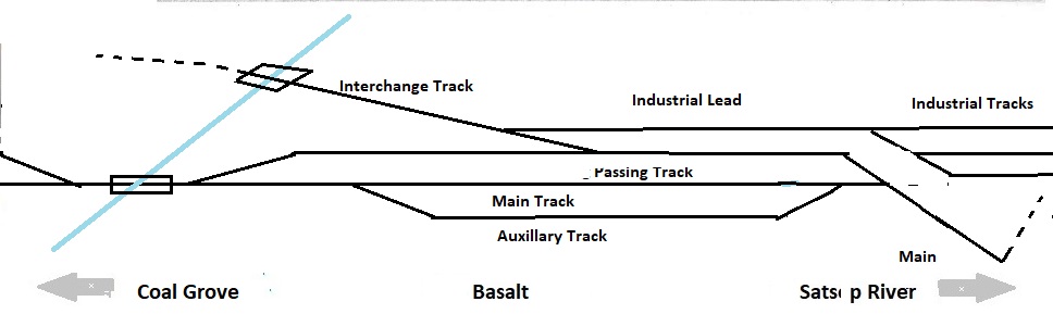
In the last blog (Module 15 - Basalt Module - Part 1) I identified the layout design elements of the Basalt Module and laid out the roadway lines. 

In this blog I am identifying the scenery construction concept and laying out the landforms.

As a refresher, here are the scenic elements.

  1. An intermediate hillside,with a basalt cliff.
  2. An embankment dropping toward an unmodeled river located along the front fascia.
  3. A stream that traverses from the fascia to the rear of the section. 
  4. A forest road that parallels the stream.
  5. A hillside is located on the north side of the stream, offset from the backdrop to hint the location of an abandoned logging roadbed.

Scenery Design Considerations

Background

The backdrop available for the Basalt section is 22 inches in height. To the south, it will be a continuation of the rain clouds on the Satsop River section. The remainder of the Basalt section will be a two part backdrop: 

  •  A blue sky with cumulus clouds suggesting a sunny day. See 5.4.1 Sky  and 5.4.2 Clouds for construction information.
  •  An Intermediate hillside. See 5.4.4 Intermediate Hills for construction information. 

Landforms

1. Basalt cliff. This is another example of needing some reinforcement to ensure the scenery is not broken in transport. The hillside is modeled with a 2 inch x 4 inch x 8 foot styrofoam panel glued to an 1/8 " luan panel that anchored to the section with rafter stiffeners. The quarry rock is a series of plaster castings. See 5.5.5 Rock Faces for additional information.  

The treeline is a combination of 3d trees and shrubs. See 5.5.7 Three Dimensional Backgrounds for construction details.


Mid-ground.  Mid-ground is flat ground with undulations suggesting bulldozing for product removal and to provide room for structures and equipment storage.

2. Embankment. Portions of the foreground between the auxiliary track and fascia is flat or sloped downward toward the Satsop River.

4. A dirt road with a improvised gate blocking traffic. See 5.9.1 Dirt Paths and Roads for construction details.

5. Intermediate hillside. This intermediate hillside begins the ridge line introducing the Coal
Grove section. Angled into the backdrop, the gap suggests the old Camp 9 right of way (now overgrown). The hillside is modeled with a 2 inch x 4 inch x 8 foot styrofoam panel. Hints of coal seams.

Waterways

3. The stream bed is multi-level with several small waterfalls. Dirt banks, gravel and small rocks in the stream. Water is created by Modge Podge. See 5.8.2 Streams for construction details.

Ground Cover

1. The areas where the sand and gravel company sand plant sits on flat land between the Satsop River and the hillside. Modeled portion includes sand plant and silos, a fuel tank, and a 2 track gravel loader. Production areas will be be gravel and dirt as appropriate. Some undulation will be formed with sculptamold.  

Vegetation

Mid-distance hillside has ground cover, shrubs, small trees.

Embankment has dirt, grass and weeds. 

Waterways

3. The stream bed is multi-layered with several small waterfalls. Dirt banks, gravel and small rocks in the stream. Water is created by Modge Podge. See 5.8.2 Streams for construction details.


Sunday, April 9, 2023

Section 15 - Basalt - Part 1

It-s time to layout the Basalt Sand and Gravel section. The layout design given and druthers of this section is identified in Station 15 Basalt.

Layout Design Elements

The Basalt Sand and Gravel section adjoins the Coal Grove section to the north and the Satsop River section to the south . It has eight scenic elements (from backdrop to fascia):

  1. A mid-distant hillside,with a basalt cliff.
  2. A sand and gravel processing plant with product piles.
  3. A main line, a primary siding track and an auxiliary siding.
  4. A spur track leading to an industrial lead serving the sand and gravel industry.
  5. An embankment located along the front fascia.
  6. A stream that traverses from the rear of the section to the fascia. 
  7. Two bridges, one on the main line and one on the industry spur track.
  8. A MOW section sited near the north switch.

Section Construction

See the WWSL section construction reference page for the construction technique. 

Basalt is a two-section set. The first section (15a) is a standard 2-foot by 8-foot section. The second section (15b) is a 2-foot by 55-inch section. Section 15b is necessary to give proper length to the main line and passing siding, and also acts as a view block between Basalt and Coal Grove.

ROW Design Considerations 

The most critical design considerations on this module is the location of the industrial lead. Its location determines the placement of the main line, a  primary siding track, and an auxiliary siding. Placing the industrial lead at 12-inches from the fascia permits both main line running and industrial switching.

3. The curved main line from the Satsop River places the Basalt main line at 7-inches from the fascia. This allows easy viewing and access. The main line must be at least seven feet in length (the longest standard operational train length).
 
The primary siding track must be located between the main line and the industry for effective car movement. This places the track at 10-inches from the fascia (the First (Northern) Division is electrified and requires catenary pole placement. It also must be at least seven feet in length (the longest standard operational train length). 

The auxiliary track is a scenic element with some operating value, but will be primarily vignette in nature. It can be located closest to the fascia. The WWSL technical specification requires a minimum 4 inches from the fascia. It should be at least three feet in length to allow for several cars to be located there for operational or vignette reasons (bad order, water cars during fire season, work train, etc.).
 
4. The industrial spur must be accessed from the primary siding track. In the WWSL history, this track is the old logging spur track going back into the timber. As an interchange track, the spur must be at least 3 feet in length to allow pick-up or set-out of up to six 40-foot cars to the industry. 

Off the industrial spur is the Basalt Sand and Gravel industrial lead. The lead services three industry sidings: two processed gravel tracks and one processed sand track. In this case, the industrial lead is approximately six feet in length, the industry sidings a minimum of two feet (processed gravel) and four feet (processed sand) respectively.
 
7. I found a temporary timber bridge made of tree trunks in the 1920's to be used as a scenic element for the industry spur bridge. Operationally, this bridge is out of service. See 4.1.9.6 Basalt Bridge N6b for construction details.

8. The main line bridge is a skewed timber trestle. I pulled up a construction diagram of a timber trestle built by the Canadian Pacific for the main line bridge. See 4.1.9.6 Basalt Bridge N6a for construction details.
 
Laying out the Structures
 
I am not going to go into great detail about laying out the structures. See the 10.0.3 Structure Layout Technique for the specific details.

The Basalt Sand and Gravel industrial is a long and narrow industrial site, located in a river valley, parallel to a shallow river. Only one portion of the portion of the industrial site is modeled: the product delivery area. The primary and secondary industrial areas (gravel pit, crushing plant, and cleaning and sorting areas) are east and south of the Basalt section and not modeled. The conveyor system is located first followed by the remaining structures. 

I created structural footprints for all the structures less the sand house itself. I have the base structure on hand and am using that for fine tuning the industrial footprint. While i was doing this I realized that I had omitted drawing in the sand house spur track. I've got to remember to add that to the track design plan. Once I have placed the sand processing plant along the industrial lead / sand track, I can finalize the two track spurs servicing the gravel loading platform.

Essentially you're going to follow this process: 

  1. Lay out the sand plant and sand silos.
  2. Lay out the conveyor system. 
  3. Lay out the oil tanks and pump house.
  4. Lay out the gravel loader.
  5. Lay out the MOW shed. 
  6. Lay out the water column.
  7. Lay out the pump house.

See the Structures Reference Page  for the specific details about building the structures.

Laying out the Right of Way

I am not going to go into great detail about putting down the roadbed lines. See the Right of Way Reference Page  for the details if you haven't had the fun of doing it before. 

Essentially you're going to follow this process: 

  1. Lay out the main line at the seven-inch line.
  2. Lay out the primary siding track at the ten-inch line.
  3. Lay out the auxiliary track at the four-inch line.
  4. Lay out the transition template for the mainline/primary siding track switch.
  5. Lay out the main line curve and turnout.
  6. Lay out the north passing siding turnout.
  7. Lay out the industrial spur.
  8. Lay out the industrial lead at 12-inches, the sand track at 14-inches, and the gravel loader tracks at nine- and seven- inches.
  9. Locate the abutments and piers for both bridges (to include heights).

Because this section ties into both the Satsop River - Section 14 and the Coal Grove - Section 16, some layout of those sections will need to be done at the same time, primarily the main line locators and the turnout positions vis-a-vis section and bridge placements etc.  

Roadway.

  • The WWSL 1st Division is designated Class B main line. See See 4.2.11.2 Modeling Technique for Medium Profile Roadway for details.
  • The WWSL auxiliary track is designated a storage track. See 4.2.11.8 Modeling Technique for Storage Track for details.
  • The WWSL industrial spur and all the Basalt Sand and Gravel spur track is designated an Industrial Lead or Spur Track. See 4.2.11.7 Modeling Technique for Industrial Lead or Spur Track for details.

Laying out the turnouts

The WWSL engineering department has authorize a non - Common Standard #6.5 Code 100 curved turnout for the south Basalt mainline to passing track. I have to ensure that the normal route leg of the turnout (26-inch radius) aligns with the primary siding track layout line at 10-inches, and the divergent leg of the turnout aligns with the main track layout line at 7-inches.

I laid out the maximum train length templates along the passing siding and main line. I have the WWSL common standard #6 turnout templates to locate main line to passing track turnouts, and main line to auxiliary siding.

I have a WWSL common standard #5 turnout to locate the industrial spur set out track. Its divergent angle conveniently angles the interchange track with the Basalt Sand and Gravel industrial lead. 

Basalt Sand and Gravel owns and maintains its own track, and uses the WWSL Common Standard #5 turnout.

Layout Drainage.  See 4.1.8 Ditches, Drains and Culverts

Drainage

Culverts

Track Details.

  • Basalt Sand and Gravel will use 4-bolt rail joiners on all track BSG uses low mount switch stands.
  • There is a double point split switch derail on the interchange track. 

In the next blog (Section 15 - Basalt - Part 2) I will discuss the Landform Design Considerations.


Sunday, April 4, 2021

Station 15 - Basalt

Location.

WWSL 1st Subdivision
Basalt (BS) is the second northernmost station on WWSL's 1st Subdivision. located at Mile Post xx.

History. Originally named Camp 9, Basalt was originally the northernmost station on the OPLC logging railroad. Logging operations were terminated in 1930 due to the Great Depression. The location was then sold to the Basalt Sand and Gravel Company

Operations.

  • The WWSL arrives at Basalt with empty hopper cars. The road locomotive pulls loads and places empties. This could be either a local train or a unit train operation. Loads will be moved to Coal Grove andd weighed on the scale track. Any cars over tonnage will need to be set off to be reduced by plant staff. Any rejected cars for mechanical failure will be spotted at the Basalt RIP track. .
  • The plant has a locomotive crane that moves cars to and from the interchange with WWSL and within the plant. Track No.1 is the sand plant. Tracks No. 2 and 3 are the gravel plant.

Design.

I wanted to show on this module a medium sized sand and gravel operations. Basalt also gave me an interesting opportunity to show a re-purposing of a railroad right of way. A logging camp layout design element would have a logging spur, a wye track for turning steam locomotives and several tracks for swapping out logging cars. This corner location on the layout plan is a good location for a wye track.  The wye could be built on the south side of the module with the two curved legs of the wye leading to the Satsop River bridge module.

A sand and gravel operation has no need for a wye, and certainly not the electrified WWSL. The WWSL's Engineering Department decided to eliminate half of the wye. The north curved leg of the wye was retained to extend the main line. The northernmost straight leg of the wye becomes the passing track. A curved turnout is added to the curved leg of the former wye to become the new mainline. A new turnout was added to repurpose the former logging car spur to become the interchange track and yard lead to three new industrial tracks now occupying the former south curved leg of the wye.  One track services the sand plant, the other two tracks service the gravel loading platform.

The northern end of Basalt where the Main, Passing and Auxiliary Tracks merge and where the xxx Creek Bridge is located is a second 5 foot module shared with Coal Grove. Coal Grove's lead Load Yard turnout is located on this module as well.

Track Diagram


Roadway. 

  • The WWSL main line will be WWSL relaxed standards.
  • The WWSL passing track will be WWSL relaxed standards.
  • The Basalt industrial trackage will be Basalt industrial track standards.

Scenery.

  • The background will be far hillside and far trees. The edge of the background will be steep embankment with mid-trees.
  • The middle ground will be flat with stone/dirt 
  • The foreground will be flat dirt.

Catenary / Signal.  

  • (C)The main line and passing track will be under wire. 
  • (C) The industrial tracks will not be under wire.

Locomotives. The Basalt plant will be switched by a BS&G locomotive crane (simulated). 

Rolling Stock. The Basalt plant requires a variety of 50, 55 and 70 ton hopper cars (HM and HT) and ballast cars (MHB). Unique cars will be 50 and 55 ton roofed hopper cars and tank cars for sand service.

Structures. Structures located at this station will be: 

  • Sand Plant with silos
  • Gravel loading Platform
  • Fuel tank
  • Water tower
  • Pump house
  • Wood logging bridge
  • Wood trestle

Reference