Sunday, September 12, 2021

Paint Right of Way

Now that I have the work space organized and cleaned for the most part, its now time to get the roadway ready for track laying. 

From looking at various construction pictures over the years, you would notice that the extruded polystyrene foam I'm using for roadway is multi-colored. Some is in its original blue (from 20 years ago), green (from the last couple of years), and a browny tan color. The browny-tan color was an earth color that Andy Sperandeo,  a contributor and late executive editor Model Railroader Magazine, recommended ina layout construction project printed in Model Railroader. His recommendation was  Burro Beige,  I think from Sherwood Williams. Not knowing my soil colors I went out and bought a gallon and liberally painted the sections I had developed to date. It was a great improvement over blue foam.

Well Burro Beige isnt on the color charts any more, so I had to cut a chunk out of my  right of way scrap pile and take it to Lowes for a computer match.  The computer does an ok job of matching but its not absolute. Your results may vary. The new color is pretty decent for a first of many layers of ground cover. 

With a roller, a 4 inch brush and a paint pan I started at one end of the layout room and started painting. The job moved right along, especially since most of the right of way is now cleared of mountains of miscellaneous supplies. It gives the room a little more of a finished look. 

In the interest of continued cleaning and organizing, I put up pre-painted fascia that had been sitting on the right of way for more than a little while. There was a giant improvement  - made me think that big things were happening.  See 3.7 Valence / Fascia for additional details. 

While I was temporarily installing the fascia, I took advantage of the opportunity and constructed a Car Card Box and Sorting Rack,  and a Pen / Uncoupler Holder. It is too early to operationally use them but having them there was an opportunity to test the concept. Another small project completed. 

With a paint job, the laying down of roadbed lines will be easier - no more guessing which line is the old line, the new line or an accidental line. My layout line strategy will be discussed at 4.2.1 Putting down layout lines. I am going to do a test section on right of way construction first to get the process down before I go live on the WWSL right of way.


Sunday, August 8, 2021

Work Spaces

Prototype Information

Class 1's have acres of dedicated work space for constructing, overhauling and repairing locomotives and rolling stock. Lots and lots of room!

One location I had the opportunity to volunteer at was the North Carolina Transportation Museum, the present name for the former Southern Railway Spencer Shops. The Shops were built in the 1890s and named after Southern Railway president Samuel Spencer. Located in Spencer, North Carolina, the Shops were a division point on the Southern Railway's main line between Atlanta GA. and points north and east. It was a main repair repair facility for those lines operating in the Carolinas, Virginia, and Georgia. It had a a 37-stall roundhouse for locomotive repairs, a back shop capable of overhauling 10 to 15 locomotives at one time, a multi-track major car repair in place, and the blacksmith shop, boiler shop, flue shop, woodworking shop, paint shop, master mechanics shop and other shop and warehouse facilities to support those operations. 


The shops ceased working on steam engines in 1953, when the railway company phased them out. Diesel repairs kept the Shops operating until more modern facilities were constructed in Chattanouga. By 1960 only the roundhouse and repair shed were still in use by less than 100 workers. Those activites were ended in 1979 and Spencer Shops was closed. The Southern Railway gifted the state of North Carolina to support the creation of the North Carolina Transportation Museum.

Modeling Information

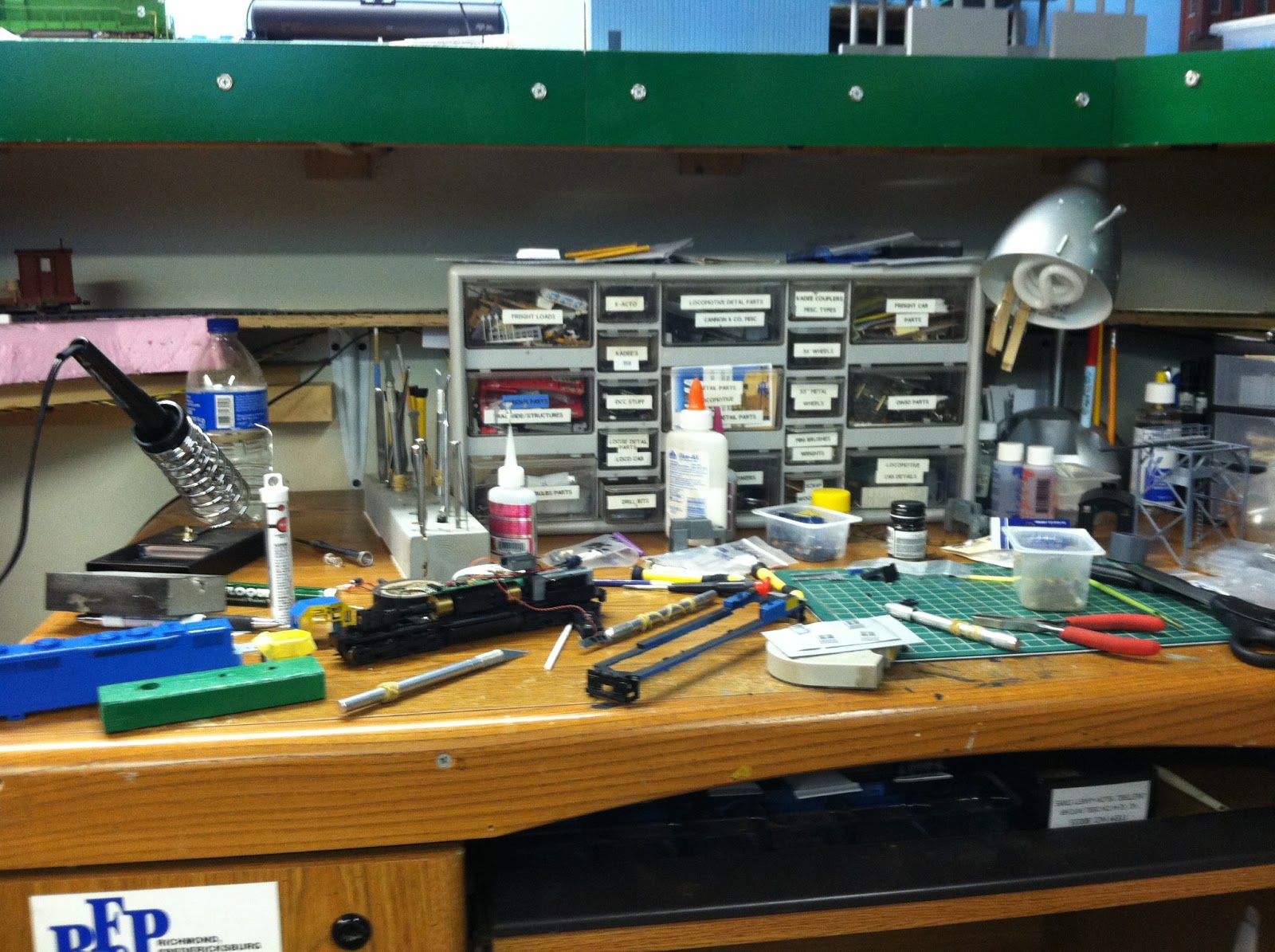
Even in 1:87th scale I don't have room for a 'prototype' facility. Economy and efficiency is the order of the day. Fortunately I have the internet and a search for railroad modeling work spaces gave me a few leads. Some railroad modelers had work desks, some had pullout work trays, one even had a modeling board and a suitcase of tools and supplies he took with him on trips. A dedicated modeler indeed!

Wherever the railroad modeler does their modeling one thing was very very clear during my search. The modeling area is universally cluttered. I'm grateful for that being the rule rather than the exception. Excepting the clutter, the ingenuity of the modeler is present.

Here are a few of my favorites.

IMG_6554
Stephan Gardiner

Ryan Mendell

_800x719.jpg
Rob McLear 


Neil Ericson

Shannon Crabtree

101_8724.JPG
Kevin Barnett

The WWSL

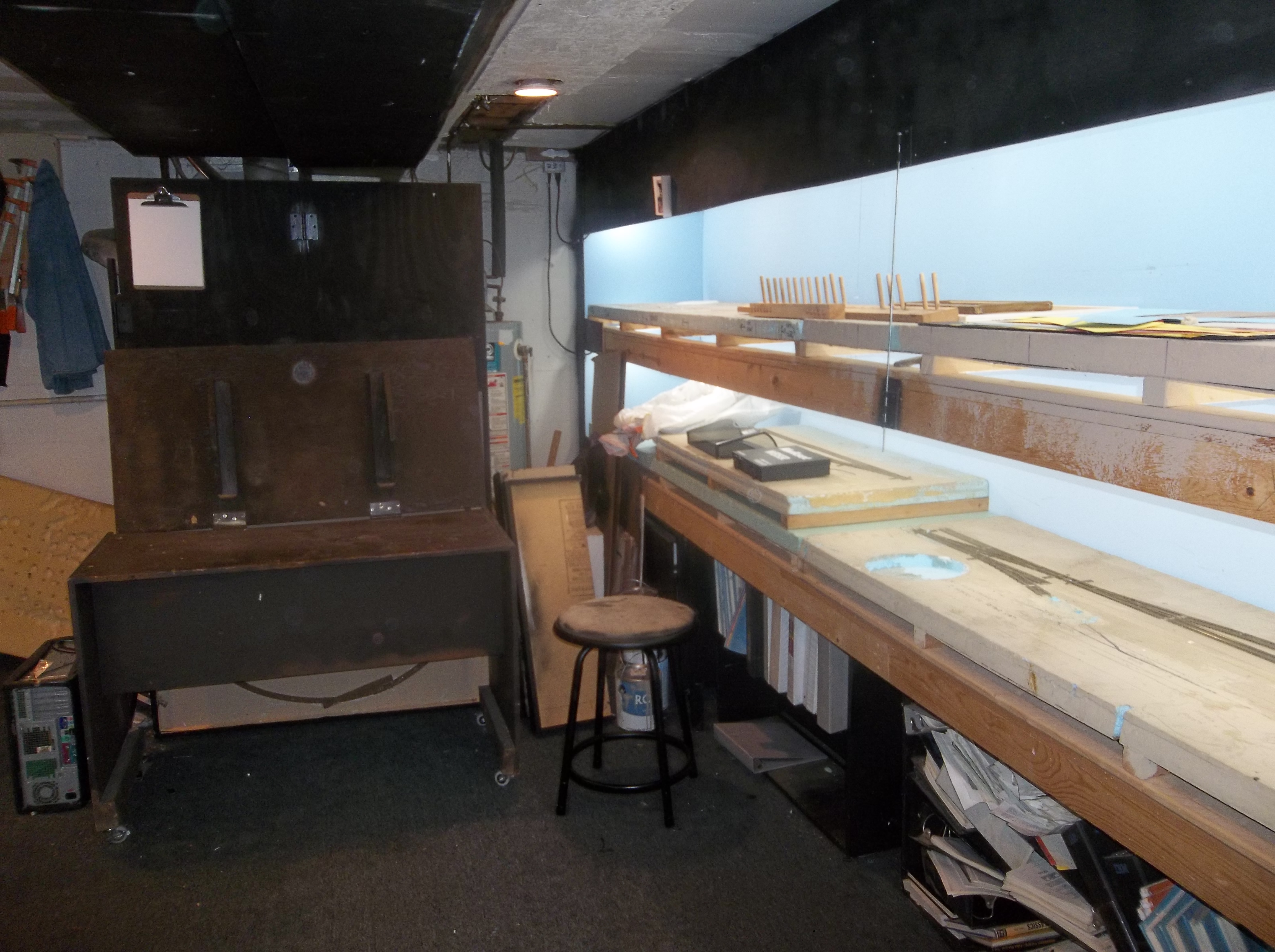
The WWSL is a moderately sized layout, and now that benchwork construction is done my modeling will now focus on right of way, scenery, locomotives and rolling stock, and structures - most of them either scratchbuilt or kitbatched. So what I need are medium sized workspaces, room for tool and supply storage, a paint booth, and plenty of good light.
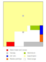
Given and Druthers

1. My work space is going to have to co-located with the utility room and the 'crew lounge'. That means being able to get to the circuit breaker box, and the set tubs (for water and washer drainage). I've got to make room for the washer and dryer. I'm going to want to have space for a dorm room sized refrigerator and coffee pot.

2. I need to have a work bench for small projects. I need space to work on larger projects. I need to have a place to store my layout sized tools. I need a place for storing locomotive and car kits, scratchbuilding and kitbatching parts (large and small). I need a place to store projects that are incomplete. I need a place to store reusable jigs. 

3. I need task oriented lighting.

4. I need vertical space to locate construction checklists, etc.

5. I need self contained construction specific workbench aids to keep the work space generally uncluttered.

6. The work space must be fairly easy to construct and maintain.

Work Bench

The work bench size must be appropriate for the work space I have allocated. The height should match the lower level of the layout for estetic reasons. The depth should be narrower so I can reach the back of the bench when seated. It should have plenty of leg room. I should have a solid top, with a support structure design such that I can clamp stuff to the front of the top as necessary. It should have the ability to clamp reference photos so they are not propped up on the bench surface taking up valuable modelling area.  See 11.1.1 Work Bench for additional details.  

Project Tables

I should have one or more tables available for larger project construction and assembly. Table should be height adjustable if possible. Table top and sides must be such that its easer to clamp tools and jigs for various projects. See 11.1.2 Project Tables for additional details. 

Project Lighting

General lighting and point lighting consistant with the layout lighting. Built in Power Bars on both sides of the bench.

Tool Storage. Tools consolidated based on project requirements. Tool bins appropriate for the project I'm working on. See 11.1.3 Tool Storage for additional details. 

Project Supplies. Supplies consolidated based on use. Cleaning supplies separate from project supplies. Supply bins appropriate for the use, size and quantity of the supplies. An overhead shelf to store small scratchbuilding and kitbatching parts and other miscellaneous stuff. Supply bins clearly labeled and easy to move. 11.1.4 Project Supplies for additional details. 

Project Storage. I know I am going to be working on multiple projects at one time. Those projects awaiting parts or waiting for the next step in the production schedule must be out of harms reach. See 11.1.5 Project Storage for additional details. 

Rolling Caddies. Some activities have to be done at the layout. I need some means of bringing selected tools and supplies to the work location, and keeping those tools and supplies organized. See 11.1.6 Rolling Caddies for additional details. 

Tool Stations. A project always goes faster when I have the right tools and supplies at hand for the job. Some tools are more important than others at any given moment. See 11.1.7 Tool Stations for additional details. 


Sunday, July 11, 2021

Clean up Work

In my last post I committed to getting back in the railroad modeling game. But to do that I have to have space to do the 400 (square foot) of small projects to improve my modeling skills. 

The good thing about having a basement for the railroad is I have space. The bad thing about having a basement is its a great place to store things .... and I stored alot of things.

  • Two rolling caddies of camping gear.
  • Five 2 and 3 shelf bookcases for books and obsolete VHS tapes (alot of tapes!).
  • Several former bedroom dressers reconfigured for draw spaces. 
  • Not one, not two, but three car drawers. See 3.14 Car Drawers for further information.
  • Three cabinets for storing car kits, structure kits, and scenery supplies.
  • Eleven 2 drawer filing cabinets for storing some 50 years of model railroad articles related to every major topic on the reference page sidebar.

Oh ! I forgot to mention the 400 square feet of shelf space that I call the WWSL ver. 3.0.

Lots and lots of stuff. Some organized but it became unorganized as time went on and I wasn't laying track. Other people call that procrastination. I plead guilty (sheepishly).

Well as my friend said ''You can only eat an elephant one bite at a time." So starting at one end, I started the clean up. Lots of clean up. The hardest part was finding the appropriate place to put it. I deliberately didn't take a before picture.

It took a while, and during that time I had to build some storage space that I knew I needed (someday) and that someday arrived. 

Half the layout room is cleaned and organized - the half that I'm going to start working on again. As time goes on, the clutter will continue to be contained, organized or gotten rid of. 


Reload, Coal Grove (top) Wickwood (bottom)


        Satsop River (top)          North River (bottom)


Polson Canyon (top)      Preachers Slough (bottom)

 While I was cleaning I decided to fix some of the stationary furniture in the room. The small table is configured as either the dispatcher's desk, or as a drafting table. It's on wheels now for easy moving as necessary. 

The two cushion couch was demoted from the living room to the crew lounge / utility room. It will be a nice place to sit when the railroading day is done and I'm marveling at my latest small project success. I ran two 2" x 4"s along the bottom and then put wheels on that  so its easy to move from the utility room to the layout space as necessary.


Roller table dispatcher configuration


Roller table draftsman configuration


Crew Lounger


"One bite (project) at a time.' Now I have to work on the workshop area to get it organized.

Sunday, June 20, 2021

Time to take a break ..... of sorts

Well it is that time of year when the retirement job I have goes full time rather than part time. 

I have finished off the layout design sequence of blog posts, and I am going to delay the construction of the modules until October when once again I will have more time to spend working on the layout. Module Construction will begin with the Satsop River module.

In the meantime, I am going to be working on the Reference Pages portion of the web site. I have alot of information I have collected over the years that is a part of the WWSL. Some of it is freely available on the internet today, some of it comes from modeling railroad internet sites that have been deleted. I will reference original sites whenever possible so you get the full value of the originator's insight. 

The text will be rough at first. It will get cleaned up over time. I hope you find information that helps you advance YOUR railroad modeling.

Sunday, June 6, 2021

Layout Design - 8 - Technical Specifications

Prototype Information

A railroad's operations is only as good as its personnel, operating plan, and its physical plant (right of way, yards, locomotive and rolling stock).

In order to ensure that each and every spect of operations is efficient, a series of documents outlining that departments operations is maintained. It is the same with the maintenance of way department.

The maintenance of way department is no exception. The department maintains a series of technical specifications on a wide variety of bridges, buildings, tools and track components used withing the railroad company system.

Fortunately there are two excellent sources of this information on the internet. 

  • Robert Schoenberg maintains a series of Pennsylvania Railroad system Standard MOW plans. 
  • Don Strack maintains a series of web pages that contains portions of the Union Pacific Common Standards book, a collection includes a large variety standards dating from 1904 to 1985.

Railroads standards were also on occasion mandated by law. I found (somewhere) a consolidated spreadsheet by state and track clearance requirements.

Check out your prototype railroad historical society or web site to see if there are standard plans applicable to your operations.

Modeling Information

The National Model Railroad Association (NMRA) has a series of Recommended Practices (RP) developed for satisfactory model operations based on existing model railroad equipment v. radii of curves and size of turnouts. Those figures, relationships or dimensions were established through actual tests and feel to be beneficial to model operation. Those recommended practices have been updated over the years, and the format I found the most interesting was RP-11, Curvature and Rolling Stock, Revised 1-90.


Andy Hamilton in the February 1991 National Model Railroad Bulletin suggested that 'Class' could be used in the hobby as a means of identifying the look and feel of the layout as it relates to operations, right of way construction and maintenance, locomotive, and rolling stock selection. 
 
Andy proposed that Prototype Class 1 operations would be expected to have broad radius curves and high speed (high number) turnouts, compared to prototype Class III operations (such as switching lines) that could be expected to have sharp radius curves and slow speed (low number turnouts).
 
The WWSL, the OPLC and the STC are Class III railroads. Using the RP format, recommendations for would identified under two Keys: 

Key F - MU and Light Electric
Key M - Standard Trunk Line
 
 
The WWSL


One day the WWSL will maintain a Common Standards book. In the meantime, you'll find those specific standards listed in the WWSL Right of Way Specifications and Modeling section of this web site. 

For general planning and construction purposes:

Human Factors. Here are the human factors used to develop the WWSL layout plan. 

Specification 

In inches

Aisle widths – normal

48

Aisle widths – constrained

30

Benchwork height – upper level

56

Benchwork height – lower level

34

Minimum track setback from Aisle

4

Minimum track setback from wall or backdrop

8

Maximum reach in distance from aisle to track

27

Bench work width for shelf style

24

Module standard width

24

Module standard length

96

Track Planning Standards.  The next step was to develop a set of standards for the trackwork. It would permit operations by virtually all HO scale equipment I would use in WWSL operations.

Specification                                     (In inches)

WWSL

OPLC

STC

Typical equipment length

40

 40

 40

Maximum equipment length

70 [1]

 50

 50

Track centers, double track, tangent

2

2

2

Track centers, tangent, Type 2 cantenary pole

3


Track centers, arrival departure track

3


Track centers, yard

2

2

2

Track centers, siding industrial track

3


Track centers, double track, minimum curve


Turnout number, single

5

6

5

Turnout number, crossover

6

8

6

Turnout number, ladder

5

6

5

Track curve, minimum radius, main line

26

26

26

Track center, double track, minimum radius


2

2

Maximum grade %

2.5


Vertical curve multiplier


Easement

28


Super-elevation

None

 None

 None

Minimum over/under track separation

3

 None

 None


Reference

NMRA recommended practices are:  


NMRA recommended practices are: RP-7 Track Centers and Obstacle Clearances RP-10 Trackwork - General RP-11 Curvature and Rolling Stock RP-12 Turnouts - General

Sunday, May 30, 2021

Layout Design - 7 - Track Plan Analysis (Part 2)

In Layout Design Process 4 - Railroad Modeling I identified that the layout design process can be broken down into three primary functional areas: Concept, Structure and Layout Detail.

Layout Detail. Layout Detail identifies the parameters within which the layout must be designed. It is broken down into two main elements: 5) Layout Design, and 6) Construction to build the railroad.
  
Under the element Layout Design, Track Plan Analysis (Part 1) considered the design against the layout given and druthers. In Track Plan Analysis (2) will be an analysis of the actual track plan as presently envisioned, and an analysis of operational trackage versus numbers of trains etc.
 
Modeling Information
 
That raised the question about car density on the layout. I found an article in Model Railroader by Roy F. Dohn that discussed a way to check the balance between main lines, yards, spurs and other trackage on a model layout. The purpose was to aid the railroad modeler in identifying the following data points:
  • Functional capacity of cars in yards and industry.
  • Functional capacity of the main line and passing tracks for movement of cars.
  •  

Data collection

The unit of measurement for this analysis is Car Capacity (CC) - the maximum number of 40' cars that can occupy each type of trackage. Actual footage doesn't work because car clearance requirements, etc. Each track is identified, measured and the data collected in spreadsheet format.

Those types of trackage to be measured were:

  • Running trackage (RT): Mainline and branchline trackage over which trains move to get to another part of the system.
  • Passing trackage (PT): Main line passing tracks, not within yard limits.
  • Maintenance and servicing trackage (MT): all trackage normally occupied by MOW cars, engine facilities, turntables, roundhouse, and similar tracks.
  • Storage trackage (ST): the total of Yard trackage (YT), Industrial trackage (IT) - basically all trackage on which equipment is stored when not running. 
  • Functional trackage (FT): trackage used for maneuvering between all the other elements - yard leads and ladders, passing and runaround tracks, inbound and outbound tracks within yard limits, and interchange tracks. 

Upon completion, the modeler has the maximum number of cars that can be physically held on the layout:  

(RTc - running trackage car capacity), 

(PTc - passing trackage car capacity),  

STCc - YTc and ITc), 

FTc


Number of cars moved (NCM) 

Cars in Service (CIS)


Data Analysis

With this information collected, the following information can be calculated: 

Storage Saturation (SS): percentage of 

Functional Saturation (FS) 

Funcgtional Main Line Saturation (FMLS):


Additional operational information is required for analysis. That information includes: 

  • Number of Cars in Service 
  • Number of Cars Moved 
  • InTransit Car Capacity Eastbound
  • InTransit Car Capacity Westbound

Once the data was entered into the database, car density was calculated and compared to a car density baseline suggested by the author. 

  • Functional Mainline Saturation (25-35%). 
  • Functional Track Saturation: (40-50%),
  • Storage Track Saturation: 33% (80-85%) ** assuming class 1 operations
  • Ideal Number of Cars is (30% of Storage tracks filled - Class 3)

The WWSL

An example

Let's use  Station 15 - Basalt for the example. Here is the Section diagram.


Measuring in 40' car length's for each track type we get the following data:


The entire WWSL layout. 

I did this for the entire WWSL layout. The results were:  

My operational information was included:

  • Number of Cars in Service  - 125
  • Number of Cars Moved - 80 (this included OPLC and STC operations)
  • InTransit Car Capacity Eastbound - 36 - (this included OPLC reload operations)
  • InTransit Car Capacity Westbound - 36 - (this included OPLC reload operations)

WWSL Analysis

 Based on the formulas in the spreadsheet, my Track Density for operations were:

  • Functional Mainline Saturation (25-35%) - 53% . 
    • InTransit Car Capacity Eastbound - (25-35%) -27% .
    • InTransit Car Capacity Westbound - (25-35%) - 24% .
  • Functional Track Saturation: (40-50%) - 25%
  • Storage Track Saturation: (80-85%) - 27%
  • Ideal Number of Cars: (30%) - 114
Analysis of the Analysis. I was surprised at how close my initial  layout planning ideas were confirmed by the data analysis.
  • Functional Mainline Saturation (25-35%) - 53% . The WWSL is a Class III railroad and has two additional Class III railroads it provides services to it. The WWSL main line is the means to getting to the customers on the line. 
  • InTransit Car Capacity Eastbound - (25-35%) -27%. This includes the OPLC reload (logging shuttle) operations, some of it on the WWSL main line. Totally consistant with Class III operations.
  • InTransit Car Capacity Westbound - (25-35%) - 24% . Again totally consistant with Class III operations. 
  • Storage Track Saturation - (80-85%) - 27%. Realizing the 80% is assuming class 1 operations, Class III operations would see primarily empty storage tracks as the norm.
  • Ideal Number of Cars -  (30%) - 114. I am using off-layout car storage for additional cars (for purposes of car interchange and car model type variety).
Reference
 
Roy Dohn, Layout plans by formula, Model Railroader, June 1968.

Sunday, May 16, 2021

Layout Design - 7 - Track Plan Analysis (Part 1)

In Layout Design Process 4 - Railroad Modeling I identified that the layout design process can be broken down into three primary functional areas: Concept, Structure and Layout Detail.

Layout Detail. Layout Detail identifies the parameters within which the layout must be designed. It is broken down into two main elements: 5) Layout Design, and 6) Construction to build the railroad.
  
Under the element Layout Design, the following area is considered: Track Plan Analysis.
 
The WWSL
 
At this point in time I have collected alot of information through the layout design process. Some of it is here and some is in the Station Plans.
 
Layout givens and druthers.
 
Concept. I am comfortable with the who what where and when aspects of the WWSL version 3.0 I particularly like the idea that i can model the three Class 1's and having the Olympic Peninsula Logging Company and the Saginaw Timber Company live and functioning is icing on the cake.


Operations. I am happy with the freight operations as envisioned. Passenger operations were considered primarily as a mechanism for building a timetable for Master Model Railroader certification. For daily operation, passenger operations is not a priority, it can be done and there are prototype examples for the trains. 
 
I believe that Demaine Yard is designed properly for a Division yard and sized appropriately for the amount of traffic going through the yard daily.

The layout design does address my interests in the natural resources industries. 'Keep it Simple Stupid' was the repeating mantra during the given and druthers stage and I think I've juggled those competing balls adequately. 

Single Track TT&TO operations can be easily implemented. The absence of a complicated signal system is a relief to me. 

An added bonus is the opportunity to model three distinct engine servicing facilities: electric, steam and diesel.


Construction. Fortunately for me I was able to recycle most of the WWSL version 2.0. Benchwork constuction was within my abilities, and new construction was about 25 percent of the layout room. Fourteen modules were reused, 12 modules were built new. 


Right of Way.
Double decking the layout was the way to go. I am comfortable with the two heights. The turnout count is high but reasonable given the degree of operating capability. Fine tuned commercial turnouts and flex track will speed up track laying. The track plan will have everything necessary for Master Model Railroader certification. 

The opportunity to build a myriad of bridges, culverts etc. is icing on the cake.
 

Scenery. A majority of the layout is flat, with scenic vignettes having most of the more 'difficult' scenery construction. It is however within my abilities. I'm looking forward to using the more modern scenic techniques employed since my construction of version 2.
 

Catenary/Signal. 
I've opted at this moment in time to model the catenary system minus the actual wire. Its not that im afraid of stringing wire, its the thought of trying to re-railing rolling stock or uncoupling them that gives me pause. Depending on my experience, I may rethink this decision after the majority of the layout is functional. 

Logically it makes sense that a short line would not have any signaling. Research indicates that the NP had an automated crossing with the Shafer Brothers rail crossing at Brady. That would entail semaphores for the NP branch line. I am thinking dwarf signals for the WWSL. The MILW/UP branch line had an automated crossing with the original Saginaw Timber Company. I am thinking dwarf signals for the WWSL there too. I'm looking at a couple of options that could be used to simulate those automated crossings.
 

 Locomotives and rolling stock. I'm looking forward to the opportunities to operate electric, steam and diesel units on the layout. Kitbatching the electric locomotives will be a skill upgrade for me. Steam locomotive operations is new and promising. I have in storage several 2-8-0's and smaller for operations. I've even got a 2-10-2 that could be used. I've got some history to justify it, but its but it's not going to be operational.
 
 
I'm pretty happy at the variety of rollling stock that can be used on the layout. I'm also looking forward to the opportunity to detail existing rolling stock and kitbatching existing cars that cannot be purchased.


Human Factors. I've always wanted a dedicated railroad layout space. Now I have it and it's met my expectations. Its fun to be down there (compared to other locations where I've had my layouts set up).  
 

Only one place has a aisle pinch point that doesn't meet the aisle parameter of a minimum 36-inch width to provide comfortable movement by crew - the right side of the layout where the workbench is located. Moving the center peninsula leftward was considered however the furnace air runs interfered with the possible construction of a stud wall and the two lally columns in the middle would interfere with personnel movement along the right center peninsula.  As it is a quick walk thru area with open space on either end for train control, the pinch point is considered a necessary evil. 
 
Having to duck under to get to the interior of the helix for track cleaning and maintenance is a necessary evil as well. Fortunately I'm still limber! 

Layout Design - 8 - Track Plan Analysis (Part 2) will be an analysis of the operational trackage versus numbers of trains, cars, etc.