Sunday, August 9, 2020

Layout Design - 0 - Designing the WWSL

In Layout Design Process 4 - Railroad Modeling I identified that the layout design process can be broken down into three primary functional areas: Concept, Structure and Layout Detail.

Layout Detail. Layout Detail identifies the parameters within which the layout must be designed. It is broken down into two main elements: 5) Layout Design, and 6) Construction to build the railroad.
  
Under the element Layout Design, the following areas are considered: 
  1. Prototype v Freelance
  2. Theme
  3. Geography
  4. Layout Design Elements
  5. Vignettes
  6. Station Maps
  7. Track Plan Analysis
  8. Technical Specifications
Under the element Construction, the following areas are considered:
  1. Room Preparation
  2. Benchwork
  3. Lighting
  4. Human Factors

Designing the WWSL 

At this point in time in my research it became clear to me that to do my railroad justice I needed to come up with a beginning and develop a corporate history that 'ends' with the era I was going to model. Based on my research I made the decision to 'interject the WWSL' into history just after World War I. The NP, the CMSTP&P (MILW), and the UP were established in Grays Harbor and were conducting business. Here is the link to the Corporate Histories page of the blog - starting with the County of Gray's Harbor, and the three Class 1 railroads, the Northern Pacific, the Milwaukee Road and the Union Pacific.

I was particularly interested in the Montesano area. Montesano was the centralized location for three logging railroads - the Schaefer Brothers Logging Company located north of the Chehelis River and the Clemons Logging Company and the Saginaw Timber Company south of the Chehelis River in what the Forestry Department names the Vesta-North River Watershed. Unfortunately none to the three logging railroads actually interchanged with the Class 1's. All three took their logging trains to log dumps along the Chehelis River, and moved the logs to the sawmills in Hoquium and Aberdeen via log rafts. Finished product was either loaded into ships to other West Coast or Asian ports of call or moved in freight trains originating in the Class 1 yards in Hoquium.

What Montesano did have that made it an ideal spot to base a short line railroad was 1) a 75 car length rail siding, and 2) a railroad bridge crossing the Chehalis River and linking the NP, MILW and UP. So let's start our alternative history with finding articles of incorporation for a logging railroad being formed east of Seattle in the Upper Green (along the Northern Pacific main line). A quick renaming within the legal documents became the source for the organization of the Olympic Peninsula Logging Company.  

 
The Olympic Peninsula Logging Company (OPLC) overlays the original rights of way of the Shaefer Brothers Logging Company in early 1920, a right of way overlay I 'imaginate' from the activities of the US Spruce Division. Research revealed that the US Spruce Division laid out plans to construct some 30 logging railroads in the Pacific Northwest to provide aircraft-grade spruce to the war effort. Only 13 were actually build and one in particular was finished on 19 days after the end of hostilities and never saw a single log hauled for the war effort. Now there's an opportunity for a budding entrepreneur! The created history of the OPLC is located here, the US Spruce Division here.
 
Using real life economics of the period and logging railroad operations in general in the Pacific Northwest lead to the creation of the Western Washington Short Line. The OPLCs business and financial activities during the Great Depression caused management to split the railroad operations into two operating companies. The WWSL came into existance as a common carrier in 1932, a not-uncommon strategy among logging railroads in other areas of the country but not in the Pacific Northwest. Common carrier was often used to condemn lands through eminent domain statutes for railroad right of way, keep out competitive logging companies, and entitle freight rate sharing adantages with connecting railroads. 

In the next blog I will discuss the concepts of prototype and freelancing modeling as they apply to the WWSL.
 

Sunday, August 2, 2020

Layout Planning - Given and Druthers Matrix


In Layout Design Process 4 - Railroad Modeling I identified that the layout design process can be broken down into three primary functional areas: Concept, Structure and Layout Detail.

Structure. Structure identifies the parameters within which the layout must be designed. It is broken down into two main elements: 3) resources available, and 4) layout planning to build the railroad.

Now that we've gone thru the process of identifing the parameters within which the layout must be designed its time to spreadsheet them so we can go to the next area of layout design - Layout Detail.

Givens


I have a number of givens:

  • Space. I am going to construct the WWSL in the 30' x 25' basement. Approximately 75 percent of the basement will be used for layout and the other 25 percent for utillities, workshop and crew lounge.


  • Scale. I am continuing to model in HO scale and will reuse my existing locomotive and rolling stock as appropriate to the WWSLs concept.
  • Finances. I have sufficient finances to initiate construction and bring the layout to completion within the time frame established.
  • Benchwork. I will recycle the benchwork I had used for WWSL v2.0
  • Modules. I will continue to use the 2' x 8' transportable modules I had used for WWSL v2.
  • Trackwork. I will continue to use Shinohara / Walthers code 83 track, turnout and special works.

Druthers


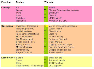
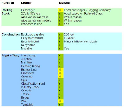
Using Bernard Kempinsk's spreadsheet format, I have outlined my druthers based on functional area.


 With these givens and druthers identified, its time to design the WWSL ver 3.0.


Saturday, August 1, 2020

OOPS !

 For some reason Modeling the WWSL hit a snag and i lost a number of blog pages. As an ex-IT guy I should have known to backup all my files but in this case I figured it would be ok and surprise -  Murphy struck!

I'm in the process of recovering my blog pages etc from a variety of sources .... and recreating a lot of content from scratch - so bear with me as you see pages from May thru late July looking pretty doggy.

I promise it'll get better !


Stan

Sunday, July 26, 2020

Layout Planning 8 - Control Parameters

In Layout Design Process 4 - Railroad Modeling I identified that the layout design process can be broken down into three primary functional areas: Concept, Structure and Layout Detail.

Structure. Structure identifies the parameters within which the layout must be designed. It is broken down into two main elements: 3) resources available, and 4) layout planning to build the railroad.

The eighth area of consideration in Layout Planning is Control.

Documentation.  Each employee knows their duties and responsibilities based on:
  • the Uniform Code; 
  • the Train Handling Instruction Manual that covers basic freight, passenger and yard operations procedures, 
  • an Employee Timetable that identifies exact train schedules and rule modifications that are in effect, 
  • Special Instructions related to the safe movement of trains, 
  • Dispatcher train sheets and Modified train order Form 19.
Operators. Personnel required are:
  • Dispatcher to issue Form 19's, develop special operating requirements and instructions such as  clearance cards, bulletins, train orders, loco fueling, within-train car placement and other prototypical elements as appropriate for operating engineers.
  • Yardmasters
  • Conductor/engineer who walk around following the train, controlling speed and direction with the hand-held throttle focused on realistic, slow speed movements and common kinds of delays, such as pumping up air brakes, setting retainers or cooling hot wheels after a steep descent. 
  • Station agent/car distributor to use waybilling process to identify car movement requirements.
Train Movement. Radio controlled block system is based on the principle that the dispatcher gives a train exclusive authority to occupy a segment of main line. As the train proceeds it gives new authority to occupy additional track and returns to dispatcher the use of track already passed. The dispatcher communicates with the crew via radio. Both Dispatcher and Conductor/Engineman have identical Form 19 (modified). By radio the Dispatcher directs the Conductor/Engineer as they fill out the form.

Car Movement.  Car movement is by waybill and switch list.

Signals. The WWSL is a busy operation, but not sufficiently so to justify any investment in a signal system. It is dark territory, operation is by Train Order Form 19, prepared by the Dispatcher. Block signals are only encountered at Montesano Junction when the WWSL crosses over the NP.

Throttle Control. DCC will be used to operate the layout. I plan to use EasyDCC wireless throttles and SoundTraxx decoders. No provision for standard DC operations is planned. The handheld compact rotary throttle units are connected to the layout through radio control.

Turnout control. The turnouts are under local control by push/pull rods at each location.


Sunday, July 19, 2020

Layout Planning -7 - Scenery Parameters

In Layout Design Process 4 - Railroad Modeling I identified that the layout design process can be broken down into three primary functional areas: Concept, Structure and Layout Detail.

Structure. Structure identifies the parameters within which the layout must be designed. It is broken down into two main elements: 3) resources available, and 4) layout planning to build the railroad.

The seventh area of consideration in Layout Planning is Scenery.

Backdrops. 

Fluorescent lighting (behind a valence) a sky-blue backdrop, a fascia panel and benchwork curtains present a net finished appearance. Backdrop 24 inches in height, colored sky blue and backdrop hand painted as necessary.

Geology.

Pacific Northwest locale - Olympic Peninsula - Grays Harbor County.

Scenery contours, foliage and other features. Conventional hard shell scenery techniques as appropriate to the geologic requirements. High ratio of scenery to track. Model relay boxes, signals, small bridges, power/telegraph poles, track bumpers, two lane roads, smaller towns, 3-4 track classification yards and small engine facilities.

Right of way and roadbed.

Cross-sections. Flattened ballast slopes, drainage ditches and fill, rivers and streams, culverts and bridges, tunnels. Relaxed standards (representing the dimensions, shapes and colors as they actually appeared during the modeled period, rather than as engineering departments specified them.

Track appearance.

Ballasted, weathered, scenicked and wired. Nut and bolt details; rail fishplates, turnout rail braces and missing hardware. Over sprayed for mineral industries, sand on uphill helper grades, litter on spur and yard clean out tracks, oil drippings in engine yards and along fueling points and spurs.

Roads and Highways.

Suitable width and curvature, horizontal and vertical easements, paved/gravel road shoulders and banking, drainage, signs and curbs as appropriate.

Structure selected.

Plausible building choices added to the layout. Use of a few detailed foreground structures that imply their presence elsewhere. Adoption of regional architecture and building materials.

Aisle Edge Decoration.

Uses the railroad's predominant official color to paint the aisle way surfaces. Use of light valence over layout as a storyboard of prototype structures, scenes, and layout sketches all tell the observer about the modeled or future intention and purpose of each area.

Sunday, July 12, 2020

Layout Planning 6 - Layout Oriented Parameters

In Layout Design Process 4 - Railroad Modeling I identified that the layout design process can be broken down into three primary functional areas: Concept, Structure and Layout Detail.

Structure. Structure identifies the parameters within which the layout must be designed. It is broken down into two main elements: 3) Resources available, and 4) Layout planning.

Under the element Layout Planning, the following area is considered: Layout Oriented Parameters.

Back in the 90's when I was a member of the Layout Design SIG the organization had a series of articles discussing the need to develop layout-oriented and people-oriented parameters to aid in the development of sincere layout design. In particular was an article written by xxxxx describing 'state of the art' model railroads. As I was thinking about the Western Washington Short Line v1.0, I used that article to come up with parameters to guide my thoughts.

Theme

  • Freelance prototype. Uses one or more prototype railroads to establish a set of guidelines and then create a railroad within the chosen framework.
  • A variety of natural resource and commercial customers (lumber, grains, fertilizers, chemical, wood chips, logs, sand, gravel, cement, coal, etc.)
  • Believable train lengths of no more than engine 8 cars and caboose. Not more than 75% of train’s cars to be to one industry.

Layout Configuration

  • Walk in with no backtracking.
  • Walls to the ceiling in a spiral pattern allow an around the room type track plan to be extended to a point-to-point distance of 100 feet.
  • Multi-tier bench work: Double decked to provide the increased main line running time.
  • Shallow design - not more than 24 inches in depth.
  • No duck-unders. No pop-up hatches

Track plan schematic

  • A point to point route, preferable avoiding any repeated use of the same track. No continuous loop operation desired.
  • Single track with multiple passing points. Several intermediate stations with passing track long enough to hold a train while others pass or meet it.
  • Terminals. A terminal at each end with facilities to accept arriving trains and hold them as well as release departing trains when required.
  • Yard Placement and Design. Small yards of no more than 3 or 4 tracks with a divisional point yard placed near the class 1 interchange.
  • Junction and Interchange. A non-operational junction with a working interchange with a Class 1 railroad.
  • Sufficient spurs and sidings to provide interesting operations.
  • Engine servicing facilities. Appropriate sized engine-servicing facilities at terminals for all locomotive types. Turntable lengths of 75 and 90 feet are suitably short for regional steam locomotives and first generational diesels.

Special features

  • Helix. Starts at 36 inches at its lowest and 60 inches at its highest . Two tracks 18 and 21 inch radius with crossover located on level 3.
  • Staging yards are provided in each end of the line and a division point yard is provided, approximately in the middle of the main line run.

Right of Way

  • Standards will be based on prototype ROW/MOW operations for appropriate class track. In the absence of prototype standards, ROW will follow NMRA standards.
  • Easy access to all turnouts and track. No hidden tracks. 

Technical Standards

  • Track Work. Track, turnouts and special works is Code 83. Main line curves are a minimum radius of 24 Visible and 21 (hidden) with spiral easements on each end. Track work will be constructed for operational perfection, but sceniced for appropriate Class I and Class III standards.
  • Grades. Grades prototypical on viewable sections. Helix grade no more than 4 percent.


Sunday, July 5, 2020

Layout Planning 5 - People oriented Parameters

In Layout Design Process 4 - Railroad Modeling I identified that the layout design process can be broken down into three primary functional areas: Concept, Structure and Layout Detail.

Structure. Structure identifies the parameters within which the layout must be designed. It is broken down into two main elements: 3) layout planning, and 4) resources available to build the railroad.

Under the element Layout Planning, the following areas are considered: 5) People oriented Parameters.

History
  •  Create a history of the railroad and its industries based on and consistant with the actural history of the region and the existing industrial base of the period.
 Operations
  •  Uses one or more prototype railroads to establish a set of operational guidelines and then create a railroad within the chosen framework.
  • Layout design to achieve believable operation with plenty of action and suitably challenging.
  • The layout to accommodate the owner and his interests and at least 4 operators for any public operating sessions.
  •  Design a walk around track plan so operators can follow their trains.
Construction
  • Construction, maintenance and operation of railroad to be within the capability of the owner.
  • L-girder benchwork. 1x3 and 1x4 L girders.
  • Benchwork based on WWSL vers 2  portable modules. Modules are connected to each other and the benchwork with alignment pins.
  • Recycle as much of the previous WWSL version 2 layout as possible. 
  • Railroad operating levels are between 38 and 58 inches above the floor allowing room for under layout storage and work space.

Control  
  • Walk around control of trains.
  • Manual control of switches whenever possible.
  • Train Order dispatching.  
  •  Use of railroad manuals etc
  • No signaling except at junctions with Class I or II railroads.

Human Factor 

  • Prepare the layout room for year round comfort and usability. Include a small crew lounge and work area.
  • Create an inviting space (I feel a layout should invite the visitor/operator into the layout space) 
  • Storage space under the layout.