Sunday, July 5, 2020

Layout Planning 5 - People oriented Parameters

In Layout Design Process 4 - Railroad Modeling I identified that the layout design process can be broken down into three primary functional areas: Concept, Structure and Layout Detail.

Structure. Structure identifies the parameters within which the layout must be designed. It is broken down into two main elements: 3) layout planning, and 4) resources available to build the railroad.

Under the element Layout Planning, the following areas are considered: 5) People oriented Parameters.

History
  •  Create a history of the railroad and its industries based on and consistant with the actural history of the region and the existing industrial base of the period.
 Operations
  •  Uses one or more prototype railroads to establish a set of operational guidelines and then create a railroad within the chosen framework.
  • Layout design to achieve believable operation with plenty of action and suitably challenging.
  • The layout to accommodate the owner and his interests and at least 4 operators for any public operating sessions.
  •  Design a walk around track plan so operators can follow their trains.
Construction
  • Construction, maintenance and operation of railroad to be within the capability of the owner.
  • L-girder benchwork. 1x3 and 1x4 L girders.
  • Benchwork based on WWSL vers 2  portable modules. Modules are connected to each other and the benchwork with alignment pins.
  • Recycle as much of the previous WWSL version 2 layout as possible. 
  • Railroad operating levels are between 38 and 58 inches above the floor allowing room for under layout storage and work space.

Control  
  • Walk around control of trains.
  • Manual control of switches whenever possible.
  • Train Order dispatching.  
  •  Use of railroad manuals etc
  • No signaling except at junctions with Class I or II railroads.

Human Factor 

  • Prepare the layout room for year round comfort and usability. Include a small crew lounge and work area.
  • Create an inviting space (I feel a layout should invite the visitor/operator into the layout space) 
  • Storage space under the layout. 

Sunday, June 21, 2020

Layout Planning 3 - Operating Style

In Layout Design Process 4 - Railroad Modeling I identified that the layout design process can be broken down into three primary functional areas: Concept, Structure and Layout Detail.

Structure. Structure identifies the parameters within which the layout must be designed. It is broken down into two main elements: 3) resources available, and 4)  layout planning to build the railroad.

The third area of consideration in Layout Planning is Operating Style.

In my post Welcome to the Western Washington Short Line  I referred to my three phases of railroad modeling. As I look back at the numerous layouts that have been published and the ones I've actually built and operated I've noticed a couple of operating styles that influences the layout design process.

The Railfan


This operating style is based on the concept that the operator is a rail fan - a line side observer  - whose interest is primarily focused on watching a series of trains move past him at a particular point of time. He has no interest in where the train was or where its going. This permits three type of layout design:
  • The oval with a single or double track main line with a yard or yards configured to hold and stage a variety of trains - passenger, freight, maintenance of way, etc - in either direction to the observer.
  • A point to point main line with staging yards at both ends configured to hold and stage the trains.
  • A figure 8 with yards or staging tracks where the crossing is a junction of two railroads.
The observer's location can be anywhere - a train station, depot, interlocking tower at a junction, even a railroad - road crossing and his operational focus is the next train on the employee timetable approaching his location. A large number of layout plans published in the model press in the 69-90's were rail fan oriented layouts.

The Engineer


This operating style is based on the concept that the operator wants to move the train from point A to point B -  starting in a yard, controlling the speed and obeying signals, meeting and passing other trains, and ending in another yard. Some local switching could occur based on the layout design.  As expected the engineers location is in the locomotive cab and his observational focus is forward - the next hill, curve, signal, station, etc.

Some of the designs of Allen, Armstrong and Wescott could be adapted to Engineer oriented layouts with selected tweaking of sidings and yards. Many of the layout plans published in the model press in the mid to late 90's  - early 2000's were Engineer oriented. The modular layout designs of clubs that show their modules at conventions, train shows etc are certainly Engineer oriented layout designs.

The Engineer/Brakeman


This operating system is based on the concept that the operator wants a greater degree of switching activity - moving the railroad car from point A to point B. The layout designs that promoted this operating system includes:
  • Switching modules ala John Allen's timesaver.
  • Lance Mindlein style industrial modules.
  • Club sized yards involves switching cars into block order at local yards.
  • Dave Barrows domino style layout designs.
This operating system gave rise to greater interest in car movement, and in particular, car card and waybill operations.  The conductor/brakeman's location is at the switch and his observational focus is the car and its movement to the car spot.

The Conductor/Engineer


What other operating system allows you the opportunity to climb off the locomotive, line the turnout, climb up on the car, ride it to the spot, tie down the brake, close the air line, pull the pin, wave the engineer off, mark the switch list, reline the turnout, climb back on the locomotive and then start all over again at a new industry spot?

This operating system is based on the concept that the operator wants to move the train from point A to point B -  controlling the speed and reacting to situations as they occur over the route - getting clearance and train orders, obeying speed limits and signals, meeting and passing other trains, reacting to weather and other operational situations imposed upon him by the scenario. As expected the engineers location is in the locomotive cab and his observational focus is forward - the next hill, curve, signal, station, etc.

This is the layout design espoused by Allen McClelland, Tony Koester and others in the model press early in the 90's but really taking off in the early 2000's thanks to the Layout Design SIG and Kalmbach publishing Model Railroad Planning and Great Model Railroads annual publications.

The WWSL Operating System. I had all three operating schemes in the layouts I built in prior years. While all provided a great deal of entertainment, it was my overwhelming preference to model a complete system influenced me greatly to implement the Conductor/Engineer operating system.

Sunday, June 14, 2020

Layout Planning 1 and 2 - Space and Scale

In Layout Design Process 4 - Railroad Modeling I identified that the layout design process can be broken down into three primary functional areas: Concept, Structure and Layout Detail.

Structure. Structure identifies the parameters within which the layout must be designed. It is broken down into two main elements: 3) resources available to build the railroad, and 4) layout planning.

Under the element Layout Planning, the following areas are considered:

  1. Space - the amount of space you have to dedicate to your layout.
  2. Scale - the physical size of the locomotives, rolling stock and structures youre going to model.
  3. Operating Style -
  4. Shape - the shape of the layout.
  5. People Oriented Parameters - specifications to be followed in the design of the laout.
  6. Layout Oriented Parameters - specifications established through the layout concept process that will be used in the design of the layout.
  7. Scenery - the type of scenery (including the absence of such) that will be incorporated in the layout.
  8. Control - the electro-mechanical control of the locomotives, the turnouts and other facets of railaroad control as part of operating the layout.

Space


Scale 

The second area of consideration in Layout Planning is Scale. Scale of the railroad model is its relative size in proportion to the real thing.The model railroading hobby presently has 6 common scales. HO scale is the most popular, N scale is second in popularity. Space is a controlling factor with respect to scale only if the available space is so limited as to make an operating layout in such a space impractical.


I have been model railroading off and on for 50 years. I started with HO scale and have modeled and operated primarily in that scale. I have had the opportunity to operate N, HO, S and O scale layouts and I find that my personal preference continues to be HO scale. 
 
The next blog will discuss operating style in the layout planning process.

Sunday, June 7, 2020

Resources 4 - Space

Over the years I've had the WWSL located in a spare bedroom in a bachelors officers quarters, a spacious attic, a large garage and most recently I bought a basement - with a house above it  - for the latest location of the WWSL. The layout started small and as fortune and space presented itself the layout grew.

Layouts are often found in garages, basements, spare bedrooms, family rooms, etc. It is humorously said that the layout location is often determined by the negotiating skills of the modeler with his significant other! 

I had a choice at this location. I had a two car garage and a basement. The garage is unheated and does not have a entry door either to the outside or to the house. Both are negatives when it comes to consideration of locating the layout. I did it with the WWSL version 2 and it was definitely a 2 season layout.

The basement is a grand 30' long by 25' wide. It has entry from inside the house and of course its heated and cooled.


Version 3.0
One square = 1 square foot
 
As basements go, its an ideal design for any large layout. The utilities (furnace and hot water heater) are located in the lower left hand corner. The stairs are at the lower right corner and the set tub, washer/dryer location and circuit breaker panel are at the center right wall. Two lally posts are located along the center line. This allows 3/4 of the basement to be used for the layout - and the other 1/4 is convenient for utilities and crew lounge/workshop. Minus the mechanical configuration of the basement (furnace, water heater, stairs and utility room area) the basement provides a footprint of some 575 square feet of space for railroad modeling.

Conveniently, its rectangular shape permitted the WWSL version 2 to 'drop' into it with no changes. The addition of 6' in length and 12' in width allows 8 additional modules for operational improvements, extended running, and greater scenic possibilities. A crew lounge and work area can be included in the final design.


Wednesday, June 3, 2020

Valence 3

In the last blog post I identified that I need some additional valences to hide the lighting bars along the peninsula. Specifically I identified the need for: 1) a 4 inch height valence added to the bottom of the end valence to hide 20 feet of light bar, and 2) a 8 inch valence attached parallel to the center beam.

I added 4 inches in depth to the end valence. This sufficiently hid the lights when looking straight down the peninsula. As it stands now there is annoying light bleed from sloppy measuring and cutting. At some point in the future i will replace this panel with a more correctly sized and cut piece. Suffice to say I'm temporarily tired of cutting panels.


The Upper Level


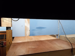
The 8 inch valence attached parallel to the center beam was an error on my part.  The upper module will not be open around the entire 180 degrees. The track goes through a tunnel at the outermost end of the module. This requires a backdrop similar to that on the rest of the upper peninsula.

I cut two luan panels to fit in preparation for constructing the peninsula modules. They solve the problem but now i have a visual issue with the end panel being observable from the side. I'm not sure whether to add some depth to the front valence at the left and and curve it into the correct height or paint the interior of the end panel black or sky blue. I'll try all three solutions and see what looks best.


Notice the electrical box on the upper right side of the picture. This was the power source for both the upper and lower peninsula deck lighting strings. I had some problems plugging the cords in and quickly realized that the hidden outlet box wasn't a good idea. Out came the box and its been reinstalled outside the valence and the cords are routed through a 2 inch hole in the valence.

The Lower Level

The lower module is open around the entire 180 degrees of the peninsula. From the observer's position, either standing or sitting, the light bar is not visible so no changes are necessary.

Sunday, May 31, 2020

Resources 3 - Money

In Layout Design Process 4 - Railroad Modeling I identified that the layout design process can be broken down into three primary functional areas: Concept, Structure and Layout Detail.

Structure. Structure identifies the parameters within which the layout must be designed. It is broken down into two main elements: 3) Resources Available to build the railroad, and 4) Layout Planning.

Under the element Resources Available, the following areas are considered: 3) Money.

Money


We generally don't talk about the cost of a layout. Our first layouts are often based on the toy train set we got as a birthday or christmas present. Plywood and 1xs dont cost much and the cost isn't calculated. As we get older we have three ways to approach budgeting:

  1. Freelance work (pay as we go) on your railroad.
  2. A set budget of what you want to spend for the railroad.
  3. No set budget and willing to pay for what you want.

Material and component selection. 


I believe that we all have at one time or another build a layout based on our financial capability at the moment. Early layouts no dobut featured sub-par materials and locomotives and rolling stock brands that looked great but ran poorly. As our financial capbility improved (and the model railroad industry improved quality) our follow-on layouts were upgraded and improved upon. A layout featuring high quality track, components, and rolling stock is a pure joy to run.

Friends over the years have asked me how much my layout cost. Frankly I hadnt kept up with the costs, 1) because it was a hobby, and 2) some stuff i bought retail, some I bought at train shows at discount, some was donated, and all of it was obtained over years in the hobby. I still have my original train set i got as a gift from my father .... its been recycled over the numerous layouts I have constructed over time.

For those who are entering the hobby for the first time, there is a cost. Model Railroader magazine has for years published entry level model railroad plans. The last entry level plan I read about was a 4x8 foot layout with DC toy train locomotive and rolling stock and basic sectional track and turnouts and a modest number of structures. The publishers indicated the price at approximately $500.00.

Custom model builders are out there willing to design and build a model railroad layout for those who dont want the thrill of benchwork construction, tracklaying, electrical wiring and scenery and structure building. One builder ranks his services as B level (basic benchwork, roadbed and track) or . Prices start at about $70 - $95 per square foot for a B Level HO or O scale layout. This would include . N scale layouts are about 50%--75% higher on a square foot basis. A or AA level quality will add 15% and 35% respectively.

The basic scenery portion of a layout (rolling hills or flat areas with grasses, dirt and gravel coverage) will add from $25 - $50 per square foot over the base price depending upon the amount of contouring. Extensive rock outcroppings or cliffs/canyons will be $55 - $100 per square foot or more additional depending on the extent of vertical coverage and level of detailing. Streams, rivers and lakes will add $35 - $90 per square foot over the base price depending upon the level of detail. Urban areas with their high concentration of structures, roads, streets, figures and details will add $55 - $120 or more per square foot to the base price depending upon the structure types and density.

As you can see, the custom costs can be astronomical. If you're doing it yourself (DIY), you will not be paying the hourly rate for the custom builder's time and effort. Those who DIY often estimate their efforts at $60 - 100 per square foot depending on the size and quality/quantity of their layout and equipment. 

WWSL costs 

 
As I have indicated earlier, the WWSL is version 3, and I have recycled alot of the benchwork, modules, trackwork, locomotives and rolling stock over the years. For this blog, I have gone back and calculated the costs of room preparation, benchwork, right of way, trackwork, locomotives and rolling stock assuming 2020 prices. Fortunately 20 years of model railroading brings with it lower entry costs and long term savings, so the pricing you see below is NOT what I've paid so far. It does however give you an indicator of current costs (or replacement costs for insurance purposes).


Room Preparation


Benchwork


Module


Trackwork


Locomotives and Rolling Stock


Wednesday, May 27, 2020

Valence 2

An interesting thing happened on the way to completing the valence on the peninsula.

The end valence is the same height as all the others. This is what you see looking lengthwise through the peninsula with the end valence in place.


This is what you see looking at the peninsula from the side aisle. I expected that the standard height valence to cover the light bar all the way down the peninsula. It doesnt.


 The end of the peninsula is an open 4-foot by 5-foot area. This new viewing depth shows all the lightbulbs and wiring. Not quite what I expected to see. From the observer's position the entire light strand is visible and very very annoying visually.


This requires two additional valences:
  1.  A 4-inch height valence added to the bottom of the end valence. This hides the 20-feet of light bar.
  2. An 8-inch valence attached parallel to the center beam. The question then became: Do i paint the valence black or sky blue? 
More next week as I consider solutions to this dilemma.