Showing posts sorted by relevance for query engineering. Sort by date Show all posts

Sunday, September 20, 2020

Layout Design - 6 - Station Maps

In Layout Design Process 4 - Railroad Modeling I identified that the layout design process can be broken down into three primary functional areas: Concept, Structure and Layout Detail.

Layout Detail. Layout Detail identifies the parameters within which the layout must be designed. It is broken down into two main elements: 5) Layout Design, and 6) Construction to build the railroad.
  
Under the element Layout Design, the following area is considered: Station Maps.

Prototye railroads use a variety of  maps to identify right of way information: track diagrams, rail and ballast information, drainage, superelevation and grade line, bridge and building, and signal and communications information. If you're fortunate to have chosen a prototype whose historical society has such maps then you are in luck. Here is my interpretatio of railroad information maps.

Engineering Maps. There are multiple examples of engineering maps. Here is one that focuses on survey information of the right of way, the track diagram includes tangent and curvature information and bridge and building information. 


One of the things i found interesting was the surveying data. Railroad engineering maps  apparently do  use civilian surveying datapoints. The route distances are calibrated on official drawings and blueprints using “stations.” These 'stations' (not to be confused with railroad timetable stations) were measured in feet and were measured from a marker placed somewhere conveniently along the line, not always at a division point. Stations are 100 feet in length. Fractions of a station are denoted by the number of feet appended with a plus sign. Thus 320+45 would be 320 stations plus 45 feet or 3245 feet, which is 0.615 mile.My youngest son found this interesting, as he is a surveyor and he uses GPS data sets on a daily basis.

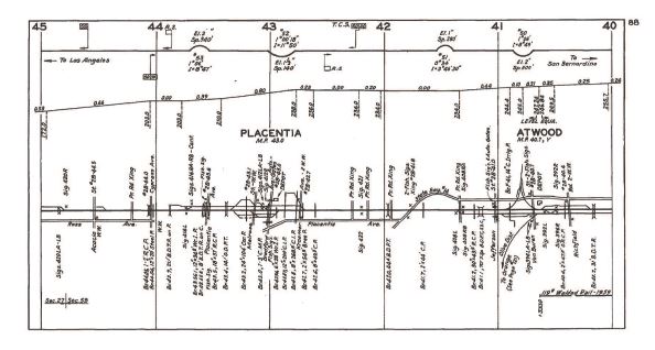
Mileage Maps.  Here is another type of engineeering map. This map focuses on (from top to bottom) track curvature, grade, track diagram, bridge and signal locations and type. If youre modeling a specific prototype location, this information is invaluable.

This mileage map displays similar information in a different format. The explanations legends are a great tool for modelers interested in the multiple types of buildings, bridge and rail used in prototype operations. I'm going to use this bridge and rail info for right of way information within this blog


There are other references to railroad activities . Here is an example of a Sanborne Insurance map that shows an industrial layout. 


 Here is an example of a cantenary engineering diagram. This will be of interest to me as one subdivision of the WWSL will be under wire. 

You're also in luck if youre modeling the early 1900's. Back between 1910 and 1925, the US government required a valuation process for all railroads. Maps were created to document the track alignments, notes were taken on structures, cuts, fills, and bridges, and photos were taken of many structures and bridges. An amazing amount of these historical materials are available to researchers in the National Archives and Records Administration in Washington, D.C.

The WWSL

The WWSL will use what I call a Station Map to consolidate railroad information. The station map of each major location will identify basic historical, operation, right of way, scenery and building elements.  As the layout progresses, the station map will be upgraded with a track diagram and right of engineering information that will meet the standards for the NMRA AP program. The section map may have one or more subsections included in the location. 
 
References

Southern Pacific Right of way and Structural Drawings

Southern Pacific Engineering Drawings


Sunday, March 5, 2023

Section 4 - Smith Canal - Part 1

It's time to lay out the Smith Canal section. The layout design given and druthers of this section is identified in Station 4 Smith Canal.

Layout Design Elements

 This section consists of eleven layout design elements:

  1. A narrow backdrop partially concealed by a coal distribution company.
  2. Waterway bank scenery adjoining the Demaine Yard and the Preacher's Slough section.
  3. A waterway that begins as a narrow stream (canal), becomes a slough and ends as a small river.
  4. A sandbank along the waterway.
  5. A single track main line going from the Demaine Yard to Preacher's Slough
  6. A beam bridge crossing over a small stream.
  7. An embankment that is the roadway for the main line between Demaine Yard and Preachers Slough.
  8. A concrete arch culvert under the embankment.
  9. A multiple span deck plate girder trestle and a concrete beam bridge crossing the waterway. 
  10. Two concrete abutments and two concrete piers.
  11. A tunnel that is bored thru a ridge line that acts as a scenic view block.
Section Construction

See the WWSL section construction reference page for the construction technique. 

As this section is a river scene I have modified the construction technique. Instead of using the two 1"x3" girders on the bottom of the section, I need a solid bottom on the section for the riverbed. The 1"x3" girders are replaced by a 2-foot by 8-foot piece of plywood, 3/4 inches thick. The two ends of the section are cut out to permit attachment of the section electrical connectors and section interface bolts.

ROW Design Considerations 

5. The most critical design considerations on this section is curvature of the main line. The turnback curve section width is 60 inches. Technical specification is a minimum 4 inches between track and the edge of the fascia. This restricts the turnback curve to 48 inches (60 - 4 - 4 = 52/2 = 26 ( a 24 inch radius when laying out the curve from the interior).

6. I'm thinking of a ATSF T-rail bridge for this location ... but that may change. See 4.1.9 Smith Canal Bridge S1 (T-rail Beam Bridge) for construction details.

7. The embankment is the second critical design consideration. This location is on top of the WWSL's DCC system and would be a convenient location for a programming track. With this in mind, the programming track 4-inches from the fascia reduces the outside embankment width and depth but allows a full embankment width and depth on the inside. 

This calculation also places the curve radius point 32-inches into the section. This leaves 11 inches for the waterway and far bank scenery. I don't see that as an issue.

8. As a continuation of the Right of Way Engineering Process I would like to engineer a concrete arch culvert. This embankment would be a perfect location. See 4.1.8 Ditches, Drains and Culverts for additional information.

9. A multiple span bridge crossing the waterway. Tentatively this will be modeled as a three span deck plate girder trestle and a concrete deck span. Most of this bridge will be on a curve, with appropriate engineering. I have a Central Valley deck plate girder trestle kit I can kitbatch. See 4.1.9 Smith Canal Bridge S2 for construction details. 

10. A portion of the 2nd Division Right of Way will not be modeled. That section is the Chehelis River Bridge and joint trackage rights with the Milwaukee Road and the Union Pacific between South Montesano and Preachers Slough. The tunnel will act as the unmodeled trackage rights portion of the WWSL. See 4.1.10.2 Tunnel S1 for construction details.

Laying out the Right of Way

I am not going to go into great detail about putting down the roadbed lines. See the Right of Way Reference Page  for the details if you haven't had the fun to do it before. 

Because this section ties into both the Demaine Yard  - Section 3 and the Preachers Slough  - Section 5, some layout of those sections (the main line locators) will need to be done at the same time, primarily the main line locator at the northern-most Preachers Slough curve (6 inches from the fascia ) and the WWSL Arrival.Departure Track at Demaine Yard (4.5 inches from the fascia).  

Essentially you're going to follow this process: 

  1. Lay out the programming track at the 4 inch line. 
  2. Lay out the main line turnback curve at the 6 inch line. 
  3. Lay out the main line to the Demaine Yard Arrival / Departure Track at the 4.5 inch line. 
  4. Center the radius at the center of the section width.
  5. Lay out the transition template line.
  6. Lay out the main line curves.
  7. Lay out the S1 bridge template and adjust as necessary.
  8. Lay out the S2 bridge template and adjust as necessary.
  9. Locate the abutments and piers (to include heights).
  10. Layout the sloped river bank on the Demaine Yard/Preachers Slough side of the waterway.

 Laying out the turnouts 

A WWSL Common Standard #6 turnout needs to be laid out on the Demaine Yard - Smith Canal module connection. WWSL technical specifications specifically requires at least two inches of straight track from the turnout to the joint, so some adjustment will have to be made.

Roadway Details
  • The WWSL 1st Division is designated Class A main line. See See 4.2.11.1 Modeling Technique for High Profile Roadway for details.
  • One of the NMRA Model Railroad Engineer - Civil certificate requirements for track work is a super elevation of the track and roadbed on a curve. While the WWSL would not prototypically use super elevation on its roadway, I am going to super elevate the curve between bridge S1 and S2 for certification purposes. See 4.2.4 Super-elevation for Curves for additional information.
  • The WWSL programming track is designated as retired track. See See 4.2.11.9  Modeling Technique for Retired Roadbed for details.
Right of Way Drainage.  See 4.1.8 Ditches, Drains and Culverts
  • Drainage
  • Culverts. The
In the next blog (Section 4 - Smith Canal - Part 2)  I will discuss the Landform Design Considerations.


Sunday, December 11, 2022

Section 12 - Tunnel 1 - Part 1

Its time to layout the Section 12 - Tunnel 1 section. The layout design given and druthers of this section is identified in Station 12 - Tunnel 1.

North Portal
South Portal


Layout Design Elements

Tunnel 1 is the lower reach of the Polson Canyon river valley. It has amoderately steep hillside and rock faces, with a sparse growth of second growth conifers, dead trees, stumps and bushes. The right of way parallels a ridge line on the east side (backdrop) and the Satsop River on the west side (fascia). The right of way tunnels through the ridge line paralleling the Satsop River and approaches the Olympic Peninsula Logging Company sawmill.

This Section consist of one module and consists of eight design elements (from geographic north to south):

  1. A single track main line from Polson Canyon to Sawmill.
  2. A curved river valley with moderately steep ridge with a sparse growth of second growth conifers, dead trees, stumps and bushes. 
  3. An embankment to the river.
  4. A heavy growth of shrubs and bushes at the river's edge. 
  5. A single track tunnel bored into a saddle in the ridge.
  6. An abandoned right-of-way (formerly OPLC main line to Camp 3) crossing the WWSL main line.
  7. A turnout off the WWSL main line to the OPLC arrival/departure track and industry complex.
  8. A 90 foot turntable owned by the OPLC in support of the Sawmill operations.

Module Construction

This section is a turnback curve portion of the WWSL layout. It is approximately 5-foot wide by 42 - inches in depth (restriction due to a lolly post).  It follows standard section construction, except it has a third 2"x2" and 1"x3" girder in the middle. The two ends of the section are cut out to permit attachment of the module electrical connectors and section interface bolts. See the WWSL section construction reference page for the construction technique.

ROW Design Considerations 

The most critical design considerations on this section is curvature of the main line. The turnback curve section width is 60 inches. Technical specification is a minimum 4 inches between track and the edge of the fascia. This restricts the turnback curve to 48 inches (60 - 4 - 4 = 52/2 = 26 (a 24 inch radius when laying out the curve from the interior).

Because this section ties into both the Section 11 - Sawmill and the Section 13 - Polson Canyon, some right of way layout of those sections will need to be done at the same time, primarily the main line locator at the southern-most Polson Canyon curve (6 inches from the fascia ) and the WWSL main line at Sawmill (4.5 inches from the fascia).

1. easement  - simple curve - Tunnel 1 - simple curve - easement  (the turnback curve).

5. Curved track within a tunnel is generally rare, but not unheard of, in the prototype. It is more common in railroad modeling layout design. The location of the tunnel and the restrictive view minimizes the suggestion of a curve within the tunnel. I have located the main line at the tunnel entrance 7 inches from the fascia. This allows 10 inches clearance at the Tunnel 1 - Polson Canyon and Tunnel 1 - Sawmill connections for turnout placement.

6. The dismantled Camp 3 logging roadway will have indications of a crossing that has been taken out. See 4.2.11.12  Modeling Technique for Dismantled Roadbed for details.

7.  

8. The turntable at Tunnel 1 was initially used by the OPLC for operations from Sawmill to Camp 9 (OPLC's western main line). Once main line operations were transferred to the WWSL, the turntable was decommissioned.  It was restored to service when the planing mill loading operation became mechanized and required boxcars to be turned. 

Laying out the Structures
 
There are five structures to be laid out: 1)  North Tunnel Portal (slide shed), 2) Tunnel Bore, 3) South Tunnel Portal (Concrete), 4) a section tool shed, a hand/motor car turn-off shed for a tunnel inspection car, and 5) a 90 foot turntable.

Tunnel 1. There are three parts to a tunnel: the tunnel portal, the tunnel bore, and the tunnel lining. See 4.1.10 Tunnels for basic tunnel engineering information.

North Portal

North Portal
The North Portal will be a re-creation of the Homestake Pass MT, west portal, NP Tunnel #5. It has a timber portal and a rock slide shed. I will represent the latter with a timber tunnel lining and a timber rock shed that extends from the portal. 
 
See 4.1.10.1a Tunnel N1 North Portal for construction details.

See 4.1.10.1b Tunnel N1 Rock Shed for construction details.

Tunnel Bore

The tunnel differs slightly from the traditional tunnel in that it has an additional height due to the electrified zone. The drainage profile will differ as well. The fascia will be removable to allow viewing of the interior. See 4.1.10.1b Tunnel N1 Tunnel Liner for construction details.

Southern Portal  

South Portal

The south tunnel entrance will be a re-creation of the April 2002 Mainline Modeler cover photo.  

The rock wall will be constructed with vertical 1 and 2 inch styrofoam insulation with a rock casting overlay.

I will represent the latter with a concrete portal. See See 4.1.10.1a Tunnel N1 South Portal for construction details.

MOW. There will be a section tool house and tunnel inspection car pull off.

Turntable

TBD

I built structure footprints for each of them for conformation of siting those structures.

Laying out Right of Way

I am not going to go into great detail about putting down the roadbed lines. See the Right of Way Reference Page  for the details if you haven't had the fun to do it before. 

Essentially you're going to follow this process: 

  1. Lay out the main line curves. It is a simple 24 inch turnback curve, with north curve at the 6-inch line, the tunnel curve at the 6-inch line, and the south curve at the 4.5- inch line.
  2. Lay out the tunnel template.
  3. Lay out the north and south tunnel portals. 
  4. Layout the northern switch to the OPLC main line and sawmill complex. 
  5. Layout the turntable approach track from the sawmill yard and spurs.
  6. Generally locate the turntable location. 

    Laying out the Turnout

    A turnout is required to connect the WWSL main line with the OPLC main line, arrival/departure track, yard lead track and and industrial spurs. Per specifications there should be at least 2 inches of straight track before reaching the module edge.

    Roadway Details 

    • Tunnel 1 Roadway is WWSL Medium Profile Roadway. See 4.2.11.2  Modeling Technique for Medium Profile Roadway for details.
    • The roadway in the tunnel bore has different drainage engineering requirements.See 4.2.11.16 Modeling Technique for Bridge Roadway for details.

    Catenary

    As this mainline is electrified, the tunnel bore and portals will have a higher clearance profile than normal. See 7.1 Cantenary Systems Overview for details.

    Right of Way Drainage.  See 4.1.8 Ditches, Drains and Culverts

    • Drainage. The tunnel will have tunnel specific drainage. See xxx.xx.xx for details.
    • Culverts

    MOW Details

    • 4.2.12.4 Hand or Motor Car Set-off Detail
    • 4.2.12.5 Rail Rests
    • 4.2.12.6 Tie Stack Detail
    • 4.2.12.7 Equipment House Detail

    Track Details.

    In addition to identifying cantenary pole locations.

    OPLC will use 4-bolt rail joiners on all track. OPLC uses medium mount switch stands.

    In the next blog (Section 12 - Tunnel 1 - Part 2) I will discuss the Landform Design Considerations.

    Reference


    Sunday, June 5, 2022

    Right of Way Section

    On the right hand side of the blog I have created a section called Reference Pages. Each aspect of model railroading has a 'section' that consolidates general and WWSL specific model railroading information.

    This month I have focused on formatting and consolidating Right of Way information. The index page is 4.0 Right of Way The following topics have been identified and sorted. Information will be updated as I get it all together.

    4.1. Railroad Engineering

    4.1.0 Right of Way 4.1.7 Special works
    4.1.1 Roadway 4.2.8 Culverts
    4.1.1.1 Roadbed 4.2.9 Bridges, Piers and Abutments
    4.1.1.2 Embankments
    4.1.10 Tunnels
    4.1.1.3 Cuts and Fills 4.1.11  Fences
    4.1.1.4 Drainage 4.1.12  Grade Crossings (Road)
    4.1.2  Ballast 4.1.13  Retaining Walls
    4.1.3  Ties 4.1.14  Car Stops / Bumper Posts
    4.1.4  Rail 4.1.15  Turntables
    4.1.5  Guardrails 4.1.16 Wyes
    4.1.6  Turnouts 4.1.17  Ash/Maint Pits

    4.2. Putting down Trackwork

    4.2.1 Putting down layout lines 4.2.8 Tunnels
    4.2.2 Laying Cork 4.2.9 Turnout Control
    4.2.3 Straight Track 4.2.10 Vertical Curves
    4.2.4 Curves 4.2.11 Track Details
    4.2.5 Turnouts 4.2.12 Painting Track
    4.2.6 Crossings and Crossovers 4.2.13 Ballasting Track
    4.2.7 Installing Under Track Items

    4.3 Construction Diagrams

    Module Station Description Length of Siding Connection
    1
    Brady Jct
    Interchange 10 cars NP
    2
    Montesano WWSL Headquarters    
    3
    Demaine Yard Class 3 Yard 18 cars  
     
    1st Division      
    8
    Schafer Prairie
    Siding Out of Service  
    9
    Camp 1 Interchange 6 cars OPLC
    10
    Headquarters      
    11
    Sawmill Siding
    6 cars
    12
    Tunnel 1      
    13
    Polson Canyon      
    14
    Satsop River      
    15
    Basalt  Siding 8 cars  
    16
    Coal Grove Class 3 Yard 16 cars
    17
    Reload Interchange 5 cars
    OPLC
       2nd Division      
    4 Smith Canal       
    5
    Preachers Slough
    Interchange
    10 cars MILW/UP
    6
    North River      
    7
    Wickwood Interchange 15 cars STC


    Sunday, April 4, 2021

    Station 15 - Basalt

    Location.

    WWSL 1st Subdivision
    Basalt (BS) is the second northernmost station on WWSL's 1st Subdivision. located at Mile Post xx.

    History. Originally named Camp 9, Basalt was originally the northernmost station on the OPLC logging railroad. Logging operations were terminated in 1930 due to the Great Depression. The location was then sold to the Basalt Sand and Gravel Company

    Operations.

    • The WWSL arrives at Basalt with empty hopper cars. The road locomotive pulls loads and places empties. This could be either a local train or a unit train operation. Loads will be moved to Coal Grove andd weighed on the scale track. Any cars over tonnage will need to be set off to be reduced by plant staff. Any rejected cars for mechanical failure will be spotted at the Basalt RIP track. .
    • The plant has a locomotive crane that moves cars to and from the interchange with WWSL and within the plant. Track No.1 is the sand plant. Tracks No. 2 and 3 are the gravel plant.

    Design.

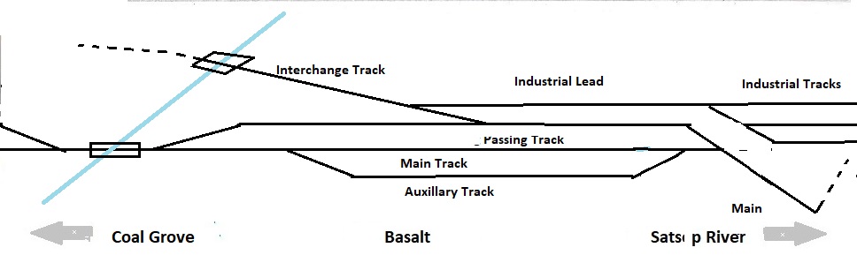
    I wanted to show on this module a medium sized sand and gravel operations. Basalt also gave me an interesting opportunity to show a re-purposing of a railroad right of way. A logging camp layout design element would have a logging spur, a wye track for turning steam locomotives and several tracks for swapping out logging cars. This corner location on the layout plan is a good location for a wye track.  The wye could be built on the south side of the module with the two curved legs of the wye leading to the Satsop River bridge module.

    A sand and gravel operation has no need for a wye, and certainly not the electrified WWSL. The WWSL's Engineering Department decided to eliminate half of the wye. The north curved leg of the wye was retained to extend the main line. The northernmost straight leg of the wye becomes the passing track. A curved turnout is added to the curved leg of the former wye to become the new mainline. A new turnout was added to repurpose the former logging car spur to become the interchange track and yard lead to three new industrial tracks now occupying the former south curved leg of the wye.  One track services the sand plant, the other two tracks service the gravel loading platform.

    The northern end of Basalt where the Main, Passing and Auxiliary Tracks merge and where the xxx Creek Bridge is located is a second 5 foot module shared with Coal Grove. Coal Grove's lead Load Yard turnout is located on this module as well.

    Track Diagram


    Roadway. 

    • The WWSL main line will be WWSL relaxed standards.
    • The WWSL passing track will be WWSL relaxed standards.
    • The Basalt industrial trackage will be Basalt industrial track standards.

    Scenery.

    • The background will be far hillside and far trees. The edge of the background will be steep embankment with mid-trees.
    • The middle ground will be flat with stone/dirt 
    • The foreground will be flat dirt.

    Catenary / Signal.  

    • (C)The main line and passing track will be under wire. 
    • (C) The industrial tracks will not be under wire.

    Locomotives. The Basalt plant will be switched by a BS&G locomotive crane (simulated). 

    Rolling Stock. The Basalt plant requires a variety of 50, 55 and 70 ton hopper cars (HM and HT) and ballast cars (MHB). Unique cars will be 50 and 55 ton roofed hopper cars and tank cars for sand service.

    Structures. Structures located at this station will be: 

    • Sand Plant with silos
    • Gravel loading Platform
    • Fuel tank
    • Water tower
    • Pump house
    • Wood logging bridge
    • Wood trestle

    Reference


    Sunday, May 21, 2023

    Section 16 - Coal Grove - Part 2

    In the last blog (Section 16 - Coal Grove - Part 1) I identified the layout design elements of the Coal Grove Section and laid out the roadway lines. 

    In this blog I am identifying the scenery construction concept and laying out the landforms.

    As a refresher, here are the scenic elements (from backdrop to fascia):

    1. A ridge line paralleling the main line.
    2. A coal processing plant.
    3. A diamond shaped coal yard with north and south leads.
    4. A scale track serving the coal and sand and gravel industry.

    Scenery Design Considerations

    Background

    The background available for the Coal Grove section is 22 inches in height, consisting of a two part backdrop: 

    •  A blue sky suggesting a sunny day. See 5.4.1 Sky for construction information.
    •  A ridge line. See 5.4.4 Intermediate Hills for construction information.

    Landforms

    Mid-ground. 

    1. Ridge. The ridge is modeled with 2 inch x 4 inch x 8 foot styrofoam panels. The ridge will have some rock faces that show traces of coal seams. See 5.5.5 Rock Faces for additional information. 

    The treeline is a combination of second growth firs  and shrubs. See xxxx for construction details. 

    2. The midground is flat ground servicing the coal yard.

    3.


     Foreground. 

    4. The foreground is flat ground with undulations suggesting prior ROW engineering and site placement for structures and equipment storage. I liked the conveyor picture suggesting that overloaded hoppers would have product removed before re-weighing.


    Sunday, June 4, 2023

    Section 17 - Reload - Part 1

    It's time to layout the Reload section. The layout design given and druthers of this section is identified in Station 17 - Reload.

    Layout Design Elements

    The Reload section is the OPLC's Camp 11. It is the 'end of track', the northernmost point of the WWSL's 1st Division. Coal Grove is the section to the immediate south. 

    Reload has eight layout design elements (from backdrop to fascia):

    1. A simple backdrop - a clear blue sky suggesting a sunny day.
    2. A close tree line.
    3. A yard lead to the Coal Grove yard. 
    4. A close tree line.
    5. A two-track logging reload spur.  
    6. A terminating main line.
    7. An interchange track.
    8. A wye track with an engine service spur on the inside.
    Module Construction

    Reload is a two-section set. The first section (17a) is a standard 2-foot by 8-foot section. The second section (17b) is a 2-foot by 4-foot section. Section 17b is connected in parallel to module 17a to deepen the section for the wye track and engine service spur.

    See the WWSL section construction reference page for the construction technique.

    ROW Design Considerations 

    Logging railroads using steam locomotives for transporting logs from the cutting sites to the sawmill have two options for train handling. The railroad can either: 1) push logging cars from the main line to the loading site, or 2) turn the locomotive at the loading site. The OPLC's standard procedure is to turn the locomotive at the loading site. Normally, the logging railroad used a wye track. Wye's require a great deal of space, and finding sufficient acreage in a mountainous forest in the Olympic Peninsula is just as difficult for the WWSL.

    I really wanted to show a logging company wye track at the end of the line.

    This wye has three specific design issues: 

    1. The north end wye leg length is only necessary to hold a steam locomotive and a water car, 
    2. The south leg needs to join the scale track (as opposed to the main line) so that the service track can be inside the wye.
    3. The west wye leg intrudes into the dispatcher's desk space (but more importantly, the utility room equipment space).

    A design alternative to a true wye track at Reload is replacing the west leg of the wye with a turntable.  I could not fine anyone doing it in the modeling press. Leaping into the abyss i am using an Atlas 65-foot turntable and literally pushing it along the west leg center line until the north and south legs intersects with two of the turntable's 30 degree radius tracks.

    The WWSL minimum engineering standards for a 2-8-0 steam locomotives using the right-of-way is 26-inch radius curves and # 6 turnouts. The railroad engineer surveyed the site to locate a triangle shaped wye places the North - South wye length 72 inches long (2*(26+10)), and the west end wye length 36 inches into the aisle. Once the west leg's  center line is established, the turntable's location can be fiddled. 

    The logging reload spurs are easy to place. The critical factor here is the two spur tracks footprint must allow for log cars and log trucks under the electric log crane structure. I suspect that the footprint is going to look like a two-lane concrete road specification rather than a two-track yard. 

    The Coal Grove North Yard lead track is a continuation of its location on Coal Grove.

    Laying out the Structures

    There are nine structures that are going to be located on this section: the locomotive servicing structures, I am not going to go into great detail about laying out the structures, as they do not affect the location of the trackage. See the 10.0.3 Structure Layout Technique for the specific details.

    Essentially you're going to follow this process: 

    1. Lay out the Electric Powered Log Crane
    2. Lay out the Water column
    3. Lay out the Oil column.
    4. Lay out the Sand column

     I created structural footprints for all the structures.

    See the Structures Reference Page  for the specific details about building the structures.

    Laying out the Right of Way

    I am not going to go into great detail about putting down the roadbed lines. See the Right of Way Reference Page  for the details if you haven't had the fun to do it before. 

    Essentially you're going to follow this process: 

    1. Lay out the main line at the 7 inch line.
    2. Lay out the secondary (scale lead) track at the 4 inch line.
    3. Lay out the north wye leg allowing for the length of the OPLC steam locomotive, a water car, and the north leg turnout.
    4. Lay out the west to north wye curve.
    5. Lay out the west to south wye curve.
    6. Lay out the south wye leg allowing for the length of the south leg turnout.
    7. Lay out the two log transfer tracks using a preferred 6 log car capacity on each track.
    8. Lay out the Coal Grove north yard lead at the 15 inch line.
    9. Lay out the WWSL interchange track. 

    Roadway.

    • The OPLC is designated Class C main line. See See 4.2.11.3 Modeling Technique for Low Profile Roadway for details.
    • The remaining OPLC trackage is designated an Industrial Lead or Spur Track. See 4.2.11.7 Modeling Technique for Industrial Lead or Spur Track for details.
    • The WWSL scale track is designated a storage track. See 4.2.11.8 Modeling Technique for Storage Track for details.

    Laying out the turnouts

    The OPLC uses #6 turnouts on all its trackage. I have to ensure that the normal route leg of the north wye turnout (26-inch radius) aligns with the main track layout line at 7 inches, and the normal route leg of the south wye turnout (26-inch radius) aligns with the scale track layout line at 4 inches.

    I laid out the OPLC locomotive/water car length templates at the end of main line location and added sufficient clearance spacing to prevent collision with the backdrop. I used Ribbon Rail and Fast Track track laying tools to locate and build in the easement and curve radius'.

    Laying out the turntable

    The Atlas Turntable has a 9 inch turntable track and its built in stall track is xx degrees. I laid out the straight line equivalent on both ends of the turntable wall to aid in the location of the turntable. There was alot of fiddling - reliable turntable operations are best when the approach track is straight to the turntable track.

    Cantenary

    The O.K. Coal north yard lead will require catenary pole placement. The OPLC trackage is not wired. See 7.1 Cantenary Systems Overview for details.

    Layout Drainage.  See 4.1.8 Ditches, Drains and Culverts

    Drainage

    Culverts

    Track Details.

    • The OPLC will use 4 bolt rail joiners on all trackage.
    • The OPLC use low mount switch stands.
    • There is a lift type derail on the service track.
    MOW Details 
     
    4.2.12.4 Hand or Motor Car Set-off Detail
    4.2.12.5 Rail Rests
    4.2.12.6 Tie Stack Detail
    4.2.12.7 Equipment House Detail

    In the next blog (Section 17 - Reload - Part 2) I will discuss the Landform Design Considerations. 
     

    Sunday, December 25, 2022

    Section 12 - Tunnel 1 - Part 2

    In the last blog (Section 12 - Tunnel 1 - Part 1) I identified the layout design elements of the Tunnel 1 Section and laid out the roadway lines. 

    In this blog I am identifying the scenery construction concept and laying out the landforms.

    Scenery Design Considerations

    Background.

    Sky, Clouds. There is 1 backdrop 22 inches in height. It will be a simple backdrops- a clear blue sky suggesting a sunny day. 

    Landforms  

    Ridge. The terrain at the North Portal will be consistent with the Polson Canyon ridge line. There is a more moderate slope along the west face of the ridge. 

    Here is the generic photograph of the southern part of Polson Canyon as it approaches the the North Portal of Tunnel 1.  

    On this section, I continued the construction of the Polson Canyon ridge line with the 2 inch styrofoam. The ridge should be at least 3x the height of the train to provide a reason for the curvature of the main line thru the river valley. Using 2 inch styrofoam insulation, this would make the rock faces at least 7 inches high with the maximum height of 11 inches for the ridge at the rear of the section.  Additional height of the ridge can be painted on the backdrop.  See 5.5.6 Mountains and 5.5.5 Rock Faces for construction details.

    Saddle

    The tunnel is sited through an enlarged saddle with basalt rock walls on both sides. The possibility of rock spalling due to steam engine smoke stack exhaust requires timber tunnel lining. No additional engineering is required within the tunnel area. 

    Tunnel Portal The terrain at South Portal will be a basalt cliff face with a concrete portal. I will use 3/4 inch styrofoam and hydrocal plaster to model the rock shelves and will use matte medium and modge podge for the waterfalls and creek. See xxxxxxx for construction details.

    Embankment. An embankment with a dry creek bed comes down the moderate hillside to the eastern river riverbank. Again, I have selectively compressed the AREA standard 60 degree angle to 45 degrees from the edge of the roadbed to the river bottom. This allows a greater river bank edge along the fascia. See 5.5.3 Embankments for construction details.

    Waterways

    Creek.

    Several streams and dry creekbeds will drain from the ridge line toward the river meandering along the the fascia.

    Once the basic land form as completed, it will be covered with Sculptamold on the flats and hydrocal plaster on the slopes. Flat areas will have some degree of undulation will be covered with sculptamold. 

    Ground Cover

    1. Far ground cover on hills and ridges will be modeled with teased and dyed felt. See for construction details.

    Near ground cover along the right of way will be a variety of dead, summer and early fall grass colors.

    Vegetation

    The hill and ridge land forms will maintain a denser growth of second growth conifers, dead trees, stumps and bushes, indications of previous logging activities 

    The embankments will have a heavy growth of shrubs and bushes, with growth along at the river's edge. See 5.7.1 Shrubs


    Draw for Tunnel 1

    Sunday, July 19, 2020

    Layout Planning -7 - Scenery Parameters

    In Layout Design Process 4 - Railroad Modeling I identified that the layout design process can be broken down into three primary functional areas: Concept, Structure and Layout Detail.

    Structure. Structure identifies the parameters within which the layout must be designed. It is broken down into two main elements: 3) resources available, and 4) layout planning to build the railroad.

    The seventh area of consideration in Layout Planning is Scenery.

    Backdrops. 

    Fluorescent lighting (behind a valence) a sky-blue backdrop, a fascia panel and benchwork curtains present a net finished appearance. Backdrop 24 inches in height, colored sky blue and backdrop hand painted as necessary.

    Geology.

    Pacific Northwest locale - Olympic Peninsula - Grays Harbor County.

    Scenery contours, foliage and other features. Conventional hard shell scenery techniques as appropriate to the geologic requirements. High ratio of scenery to track. Model relay boxes, signals, small bridges, power/telegraph poles, track bumpers, two lane roads, smaller towns, 3-4 track classification yards and small engine facilities.

    Right of way and roadbed.

    Cross-sections. Flattened ballast slopes, drainage ditches and fill, rivers and streams, culverts and bridges, tunnels. Relaxed standards (representing the dimensions, shapes and colors as they actually appeared during the modeled period, rather than as engineering departments specified them.

    Track appearance.

    Ballasted, weathered, scenicked and wired. Nut and bolt details; rail fishplates, turnout rail braces and missing hardware. Over sprayed for mineral industries, sand on uphill helper grades, litter on spur and yard clean out tracks, oil drippings in engine yards and along fueling points and spurs.

    Roads and Highways.

    Suitable width and curvature, horizontal and vertical easements, paved/gravel road shoulders and banking, drainage, signs and curbs as appropriate.

    Structure selected.

    Plausible building choices added to the layout. Use of a few detailed foreground structures that imply their presence elsewhere. Adoption of regional architecture and building materials.

    Aisle Edge Decoration.

    Uses the railroad's predominant official color to paint the aisle way surfaces. Use of light valence over layout as a storyboard of prototype structures, scenes, and layout sketches all tell the observer about the modeled or future intention and purpose of each area.

    Sunday, April 9, 2023

    Section 15 - Basalt - Part 1

    It-s time to layout the Basalt Sand and Gravel section. The layout design given and druthers of this section is identified in Station 15 Basalt.

    Layout Design Elements

    The Basalt Sand and Gravel section adjoins the Coal Grove section to the north and the Satsop River section to the south . It has eight scenic elements (from backdrop to fascia):

    1. A mid-distant hillside,with a basalt cliff.
    2. A sand and gravel processing plant with product piles.
    3. A main line, a primary siding track and an auxiliary siding.
    4. A spur track leading to an industrial lead serving the sand and gravel industry.
    5. An embankment located along the front fascia.
    6. A stream that traverses from the rear of the section to the fascia. 
    7. Two bridges, one on the main line and one on the industry spur track.
    8. A MOW section sited near the north switch.

    Section Construction

    See the WWSL section construction reference page for the construction technique. 

    Basalt is a two-section set. The first section (15a) is a standard 2-foot by 8-foot section. The second section (15b) is a 2-foot by 55-inch section. Section 15b is necessary to give proper length to the main line and passing siding, and also acts as a view block between Basalt and Coal Grove.

    ROW Design Considerations 

    The most critical design considerations on this module is the location of the industrial lead. Its location determines the placement of the main line, a  primary siding track, and an auxiliary siding. Placing the industrial lead at 12-inches from the fascia permits both main line running and industrial switching.

    3. The curved main line from the Satsop River places the Basalt main line at 7-inches from the fascia. This allows easy viewing and access. The main line must be at least seven feet in length (the longest standard operational train length).
     
    The primary siding track must be located between the main line and the industry for effective car movement. This places the track at 10-inches from the fascia (the First (Northern) Division is electrified and requires catenary pole placement. It also must be at least seven feet in length (the longest standard operational train length). 

    The auxiliary track is a scenic element with some operating value, but will be primarily vignette in nature. It can be located closest to the fascia. The WWSL technical specification requires a minimum 4 inches from the fascia. It should be at least three feet in length to allow for several cars to be located there for operational or vignette reasons (bad order, water cars during fire season, work train, etc.).
     
    4. The industrial spur must be accessed from the primary siding track. In the WWSL history, this track is the old logging spur track going back into the timber. As an interchange track, the spur must be at least 3 feet in length to allow pick-up or set-out of up to six 40-foot cars to the industry. 

    Off the industrial spur is the Basalt Sand and Gravel industrial lead. The lead services three industry sidings: two processed gravel tracks and one processed sand track. In this case, the industrial lead is approximately six feet in length, the industry sidings a minimum of two feet (processed gravel) and four feet (processed sand) respectively.
     
    7. I found a temporary timber bridge made of tree trunks in the 1920's to be used as a scenic element for the industry spur bridge. Operationally, this bridge is out of service. See 4.1.9.6 Basalt Bridge N6b for construction details.

    8. The main line bridge is a skewed timber trestle. I pulled up a construction diagram of a timber trestle built by the Canadian Pacific for the main line bridge. See 4.1.9.6 Basalt Bridge N6a for construction details.
     
    Laying out the Structures
     
    I am not going to go into great detail about laying out the structures. See the 10.0.3 Structure Layout Technique for the specific details.

    The Basalt Sand and Gravel industrial is a long and narrow industrial site, located in a river valley, parallel to a shallow river. Only one portion of the portion of the industrial site is modeled: the product delivery area. The primary and secondary industrial areas (gravel pit, crushing plant, and cleaning and sorting areas) are east and south of the Basalt section and not modeled. The conveyor system is located first followed by the remaining structures. 

    I created structural footprints for all the structures less the sand house itself. I have the base structure on hand and am using that for fine tuning the industrial footprint. While i was doing this I realized that I had omitted drawing in the sand house spur track. I've got to remember to add that to the track design plan. Once I have placed the sand processing plant along the industrial lead / sand track, I can finalize the two track spurs servicing the gravel loading platform.

    Essentially you're going to follow this process: 

    1. Lay out the sand plant and sand silos.
    2. Lay out the conveyor system. 
    3. Lay out the oil tanks and pump house.
    4. Lay out the gravel loader.
    5. Lay out the MOW shed. 
    6. Lay out the water column.
    7. Lay out the pump house.

    See the Structures Reference Page  for the specific details about building the structures.

    Laying out the Right of Way

    I am not going to go into great detail about putting down the roadbed lines. See the Right of Way Reference Page  for the details if you haven't had the fun of doing it before. 

    Essentially you're going to follow this process: 

    1. Lay out the main line at the seven-inch line.
    2. Lay out the primary siding track at the ten-inch line.
    3. Lay out the auxiliary track at the four-inch line.
    4. Lay out the transition template for the mainline/primary siding track switch.
    5. Lay out the main line curve and turnout.
    6. Lay out the north passing siding turnout.
    7. Lay out the industrial spur.
    8. Lay out the industrial lead at 12-inches, the sand track at 14-inches, and the gravel loader tracks at nine- and seven- inches.
    9. Locate the abutments and piers for both bridges (to include heights).

    Because this section ties into both the Satsop River - Section 14 and the Coal Grove - Section 16, some layout of those sections will need to be done at the same time, primarily the main line locators and the turnout positions vis-a-vis section and bridge placements etc.  

    Roadway.

    • The WWSL 1st Division is designated Class B main line. See See 4.2.11.2 Modeling Technique for Medium Profile Roadway for details.
    • The WWSL auxiliary track is designated a storage track. See 4.2.11.8 Modeling Technique for Storage Track for details.
    • The WWSL industrial spur and all the Basalt Sand and Gravel spur track is designated an Industrial Lead or Spur Track. See 4.2.11.7 Modeling Technique for Industrial Lead or Spur Track for details.

    Laying out the turnouts

    The WWSL engineering department has authorize a non - Common Standard #6.5 Code 100 curved turnout for the south Basalt mainline to passing track. I have to ensure that the normal route leg of the turnout (26-inch radius) aligns with the primary siding track layout line at 10-inches, and the divergent leg of the turnout aligns with the main track layout line at 7-inches.

    I laid out the maximum train length templates along the passing siding and main line. I have the WWSL common standard #6 turnout templates to locate main line to passing track turnouts, and main line to auxiliary siding.

    I have a WWSL common standard #5 turnout to locate the industrial spur set out track. Its divergent angle conveniently angles the interchange track with the Basalt Sand and Gravel industrial lead. 

    Basalt Sand and Gravel owns and maintains its own track, and uses the WWSL Common Standard #5 turnout.

    Layout Drainage.  See 4.1.8 Ditches, Drains and Culverts

    Drainage

    Culverts

    Track Details.

    • Basalt Sand and Gravel will use 4-bolt rail joiners on all track BSG uses low mount switch stands.
    • There is a double point split switch derail on the interchange track. 

    In the next blog (Section 15 - Basalt - Part 2) I will discuss the Landform Design Considerations.