In the last blog (Section 6 - North River Bridge - Part 1) I identified the layout design elements of the North River Bridge Module and laid out the roadway lines.
In this blog I am identifying the scenery construction concept and laying out the landforms.
As a refresher, here are the scenic elements.
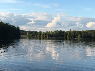
- A sunny sky.
- A distant treeline with a river disappearing in the distance.
- A low dam in the background.
- A wide deep river with relatively high river bank.
- A lower river area expanding into the delta area.
Scenery Design Considerations
Background
The backdrop available for the North River Bridge section is 22 inches in height.
1. A blue sky with cumulus clouds suggesting a sunny day. See 5.4.1 Sky and 5.4.2 Clouds for construction information.2. A distant tree line. See 5.4.6 Closer Hills and 5.4.9 Conifer Trees for construction information.
Landforms
Midground
The right of way parallels the terrain along the ridge line. The terrain on the near side of the right of way has been engineered as an embankment.
Foreground
The remainder of the forground is open ground, either flat or sloped downward toward the fascia.
Creating the Landforms
Background Landmass
Just like the Satsop River build, I built two small roadbed panels
and installed them at the module ends, leaving the center roadway / waterway area clear.
4. Upper river bank. Upon installation of the dam, the rest of the upper riverbank was fairly straight forward The river bank carved and shaped to about a 45 degree angle. I used a drywall knive and the Stanley Surform scraper for this step. The shreds of foam were messy but easier to clean up than sanding conventional plaster.
5. Lower river bank. The north river bank (right) and the south river bank (left) are manmade embankment. The AREA standard for an embankment is a 60 degree angle from the edge of the roadbed to the river bottom. See 4.1.1.2 Embankments for construction details. Using to total length of the bridge complex, I will locate the south abutment and cut it in. Pieces of styrofoam and expanding foam will complete the basic landform.
Once I figure out where the bridge abutments are located, I can
shape the river and the river banks, adding foam as necessary. The
embankments are formed with the 2 inch styrofoam and open spaces under
the masonite and above the plywood are filled with 2 inch stryofoam cut
to fit, and using expanding foam as necessary.
Waterways
The head dam
3. A low head dam, sometimes simply called a weir, is a small structure that impounds a small amount of water and spans the width of river or stream. Usually made from concrete, the purpose of a low head dam is to raise the water level upstream on a river. In this particular case, the WWSL history has indicated it is one of several dams on the North River that provide a reservoir for American Pulp and Paper Company operations.
4. The head dam is anchored on the high terrain on either side of the river bank. The river bank has a height of 4 inches, the height of the head dam is three inches. See 10.xx.xx for construction details.
3. I
am currently considering my options for completing the river I haven't
decided whether to pour epoxy water or use a combination of paint and
matte and gloss medium. Ive got plenty of time to make that decision. By its very nature there will be three techniques used:
- The upper waterway will be created by . See 5.8.x Lake for construction details.
- The water fall over the dam will be created with xxx. See 5.8.6 Waterfall for construction details.
- The lower river will be See 5.8.4 River (Deep) for construction details.
Reference


.JPG)

No comments:
Post a Comment