Sunday, April 4, 2021

Station 15 - Basalt

Location.

WWSL 1st Subdivision
Basalt (BS) is the second northernmost station on WWSL's 1st Subdivision. located at Mile Post xx.

History. Originally named Camp 9, Basalt was originally the northernmost station on the OPLC logging railroad. Logging operations were terminated in 1930 due to the Great Depression. The location was then sold to the Basalt Sand and Gravel Company

Operations.

  • The WWSL arrives at Basalt with empty hopper cars. The road locomotive pulls loads and places empties. This could be either a local train or a unit train operation. Loads will be moved to Coal Grove andd weighed on the scale track. Any cars over tonnage will need to be set off to be reduced by plant staff. Any rejected cars for mechanical failure will be spotted at the Basalt RIP track. .
  • The plant has a locomotive crane that moves cars to and from the interchange with WWSL and within the plant. Track No.1 is the sand plant. Tracks No. 2 and 3 are the gravel plant.

Design.

I wanted to show on this module a medium sized sand and gravel operations. Basalt also gave me an interesting opportunity to show a re-purposing of a railroad right of way. A logging camp layout design element would have a logging spur, a wye track for turning steam locomotives and several tracks for swapping out logging cars. This corner location on the layout plan is a good location for a wye track.  The wye could be built on the south side of the module with the two curved legs of the wye leading to the Satsop River bridge module.

A sand and gravel operation has no need for a wye, and certainly not the electrified WWSL. The WWSL's Engineering Department decided to eliminate half of the wye. The north curved leg of the wye was retained to extend the main line. The northernmost straight leg of the wye becomes the passing track. A curved turnout is added to the curved leg of the former wye to become the new mainline. A new turnout was added to repurpose the former logging car spur to become the interchange track and yard lead to three new industrial tracks now occupying the former south curved leg of the wye.  One track services the sand plant, the other two tracks service the gravel loading platform.

The northern end of Basalt where the Main, Passing and Auxiliary Tracks merge and where the xxx Creek Bridge is located is a second 5 foot module shared with Coal Grove. Coal Grove's lead Load Yard turnout is located on this module as well.
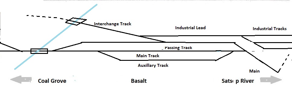
Track Diagram


Roadway. 

  • The WWSL main line will be WWSL relaxed standards.
  • The WWSL passing track will be WWSL relaxed standards.
  • The Basalt industrial trackage will be Basalt industrial track standards.

Scenery.

  • The background will be far hillside and far trees. The edge of the background will be steep embankment with mid-trees.
  • The middle ground will be flat with stone/dirt 
  • The foreground will be flat dirt.

Catenary / Signal.  

  • (C)The main line and passing track will be under wire. 
  • (C) The industrial tracks will not be under wire.

Locomotives. The Basalt plant will be switched by a BS&G locomotive crane (simulated). 

Rolling Stock. The Basalt plant requires a variety of 50, 55 and 70 ton hopper cars (HM and HT) and ballast cars (MHB). Unique cars will be 50 and 55 ton roofed hopper cars and tank cars for sand service.

Structures. Structures located at this station will be: 

  • Sand Plant with silos
  • Gravel loading Platform
  • Fuel tank
  • Water tower
  • Pump house
  • Wood logging bridge
  • Wood trestle

Reference


Sunday, March 21, 2021

Station 14 - Satsop River

Location. Satsop River Bridge is located on WWSL's 1st Subdivision Mile Post xx.

WWSL 1st Subdivision
Approaching the Satsop River from the south (actual compass heading is west) the single track WWSL mainline runs along a long fill to cross over the river on a 300 ft long bridge made up of four plate girder sections on the east side of the river, and a timber trestle section on the west side. The west end of the bridge leads to the top of a bluff overlooking the west shore.

History.

Originally OPLC main line to Camp 9. The first bridge was a timber trestle that burned in 1929. The second bridge was a two span Howe wood truss bridge that was replaced in 1939 because it was inadequate to the loads.

Vignette. The Satsop River is a vignette. It is a recreation of the Tacoma Eastern bridge at Morton Washington.


Design. The track plan consists of a fill approach on the each bank, four deck plate girder bridges over the river, then a wood trestle reaching the west bank of the river. At both ends of the track plan are the decommissioned wye tracks that once supported logging operations at OPLC Camps 7 and 9.

Track Diagram


Roadway.  Both approach tracks (north and south) will have the remnants (old ties and ballast) of wye turnouts that once serviced OPLC Camps 7 and 9. 

The following bridges, piers and abutments will be required:

  • 1 Concrete Abutment
  • 1 x 90 foot Steel Deck Girder Bridge
  • 2 x 65 foot Steel Deck Girder Bridges
  • 1 x 90 foot Steel Deck Girder Bridge
  • 1 x' 60 Wood Timber Trestle 
  • 1 Wood Abutment
  • 4 Misc Construction Piers

Scenery. Per photograph.

Sunday, March 14, 2021

Section Construction is Completed !

As discussed previously, 16 of my right of way sections were recycled from my previous layout WWSL ver. 2.0. I had to construct  12 new right of way sections. Those sections were:

Division 1

  • Schafer Prairie (Helix)
  • Camp 1 Section (2)
  • Headquarters Section  (1)
  • Sawmill Section (2)
  • Tunnel 1 Section (1)
  • Polson Canyon Section (2)
  • Satsop River Section (1)
  • Basalt Section (2)
  • Coal Grove Section (1)
  • Reload Section (1)

Division Point 

  • Brady Section  less the traversing tables (transfer table) (2)
  • Montesano Section  (1)
  • Demaine Yard Section (2)

Division 2

  • Chehelis River Section (1)
  • Preachers Slough Section (2) 
  • North River Section (1)
  • Wickwood Section (4)
All sections have been upgraded to WWSL ver.3.0 (See Section / Module Design ).


Sunday, March 7, 2021

Station 13 - Polson Canyon


Location. Polson Canyon is located on WWSL's 1st Subdivision Mile Post xx.
WWSL 1st Subdivision

Vignette. Polson Canyon is a vignette. It is a recreation of the Milwaukee Road's

Design. I wanted to create a winding main line along the Middle Satsop River similar to the Milwaukee Roads main line thru xxxxx and yyyy, with the Olympic Peninsula terrain rather than the rugged terrain shown in the pictures below. 


The south entrance to the canyon is a wooden tunnel portal with rock shed, similar to the Northern Pacific's West Portal Tunnel #5, Homestake Pass, MT.

The main line is a series of 32 degree curves paralleling the Middle Fork of the Satsop River.
The north entrance to the canyon as it approaches the Satsop River Bridge has two abandoned spurs, originally built to service OPLC Camps 5 and 7.

Track Diagram.


Roadway.  Main line is WWSL main line relaxed standard.

  • Bridge 1 is a 50 ' thru plate girder bridge
  • Bridge 2 is a 65' thru plate girder bridge.
  • Bridge 3 is a 60' timber trestle on either side of a 50' deck girder bridge.

The roadbed to Camp 5 is OPLC abandoned. The roadbed to Camp 7 is OPLC ties and dirt roadbed.

Scenery.

  • Far scenery is high hillside with secondary forest growth.
  • Mid scenery is near vertical basalt cliffs and dirt embankments as appropriate.
  • Near scenery is river embankment with post-cutting scrub growth.

Catenary/Signaling. The main line is under wire.

Structures. 

  • The south entrance to Polson Canyon will have a wooden tunnel portal with rock shed, similar to the Northern Pacific's West Portal Tunnel #5, Homestake Pass, MT.
  • If possible, a slide fence will be along the verticle basalt cliff.
  • The north entrance to Polson Canyon may have a MOW scene, TBD.

REFERENCES.

Joel's Southern Pacific in The Cascades, http://spcascades.railfan.net/NP.html

Sunday, February 21, 2021

Station 12 - Tunnel 1

Location.

WWSL 1st Subdivision
Tunnel 1 is located on WWSL's 1st Subdivision Mile Post xx.

History. The idea of a logging railroad having tunnels seems remote but there have been good reasons for loggers to build tunnels. The Olympic Peninsula in Washington State had three operational logging tunnels.

  • Clemons Logging Company had a tunnel in the vicinity of Melbourne. It was built in 1922-23. [1]
  • The Port Angeles and Western (originally Olympic Spruce Railroad #1) had two tunnels - the Daley-Rankin bore and the 46 foot McFee bore built in 1917-1918. They were operational for 36 years.  [2]

Design. Tunnel 1 has two functions. First (South Portal) it is the end point of the Station 11 (OPLC) module and contains a 90 foot turntable in support of the Sawmill operations. Second (North Portal) it is the start point for the Station (13) Polson Canyon Module. 

Track Diagram


Roadway.  

  • WWSL 1st Division is WWSL Medium Profile Roadway.
  • WWSL Tunnel 1 will be WWSL electrified tunnel Common Standard and will have a rerailing fixture at both entrances. 

Scenery.

South Portal

The south tunnel entrance will be a re-creation of the April 2002 Mainline Modeler cover photo.The backdrop will be medium blue sky. The far scenery will be the basalt rock formation shown on the cover. The mid and near scenery will be level ground.

The tunnel itself will be a wood paneled tunnel lining upgraded in 1953 with a concrete portal and gunnite lining. The fascia will be removable to allow viewing of the interior.


North Portal

The North Portal will be a re-creation of the Homestake Pass MT, west portal, NP Tunnel #5. [3]

 The backdrop will be medium blue sky. The far scenery will be a basalt rock formation. The mid scenery will be a mountainous terrain dropping to track level. The near terrain will be a cut to river level.


Catenary / Signal. 

  • (C)  The main line will be wired. The turntable, the approach track and any storage tracks will not be wired.


Rolling Stock.

Maintenance of way operations will require a hopper car with an icicle removal frame. If there is room, a tunnel maintenance inspection car could be added.

Reference:

[1]Vesta - Little North River WSA - compiled for the US Forest Service by Tim Scherer, Team Leader WSA

[2] Fading Memories, Model Railroad Craftsman, October 2000.

[3] West Portal Tunnel No.5 Homestake MT, Joel's SP In The Cascades

Sunday, February 14, 2021

Modular vs Sectional Design

Modeling Information

There are two types of layouts, movable and immovable. Having been in the military for 14 years and moved some 8 times in those 14 years, I opted for a movable type of layout. I've moved it three times in the next 20 years as a civilian. 

There are two types of movable layouts: modular and sectional.

Modular Type A. By definition,  a module is a section of benchwork and roadbed that is built to  common standard determined by the organization establishing the standard. Modules fit together with standard track connections at the ends, but builders can construct any kind of scene on a given module. - as long as one module fits against another module railwise. Modelers are generally confined to fixed-length modules of 4, 6, or 8 feet long.

Ntrak is one of the modeling organizations that has created a commond standard and other modeling groups have developed standards of their own. Those layouts you see at train shows and flea markets are modular type A layouts.

Modular Type B. Another group that does modular but differently is Fre-mo. Free-mo was developed with the idea that allows the modeler’s creativity to shine through their modules.  The Free-mo standard focuses mainly on the module end plates. The Free-mo mainline is centered on a two foot end so modules can be inverted 180 degrees and still mate up to the adjacent module without modification to wiring or track. This allows modeling of prototype track plans and operations in a modular environment. The length and track configuration of a Free-mo module or module set is up to the modeler as long as the module end plate standard is followed. .

Sectional. Sectional design assumes that the layout is going to be moved at some point. Unlike modules, the sectional layout does not follow any standard track pattern because the pieces need to fit together only one way. The scenery can maintain continuity from section to section following the theme of your railroad.

Benchwork is the same, the only difference is the connection points are designed with a move in mind. Assuming you don’t have to take your show on the road very often, you don’t even have to leave breaks in the track and scenery at section joints. When it’s time to move, simply cut the rails and slice through the terrain. As long as you have some extra track and scenery materials on hand, you’ll be able to “heal” the scars at the section joints

Dominos. David Barrow devised a sectional construction system using standardized rectangular layout segments (think table layout that disassembles). He likes to lay out track plans by fitting these sections together end to end and forming 90-degree corners, so the comparison to the game of dominoes was obvious. He’s  described his domino method in both Model Railroader and Model Railroad Planning articles. The illustration shows the basic form of domino layout sections.

The WWSL

WWSL ver. 2.0 was several concepts wrapped up in one. I wanted modular construction that would be easy to move . I was taken with the idea presented by David Barrows about 'domino's. His choices for his layout was:

  • Segmental benchwork construction.
  • Minimalist design aesthetics rather than a realistic scenicked railroad.
  • Wide aisles.
  • Finished open room with carpeted floor.
  • Off-the-shelf unpainted code 100 flex track and no. 6 turnouts operatied by manual ground throws to minimize wiring and complexity.

This made a lot of sense to me - after all all my layouts to date had essentially been minimalist designs rather than realistic scenicked railroads. Heck, I hadn't even painted the plywood green!

This minimalist idea was followed by Tony Koesters Layout Design Elements That allowed me the opportunity to develop a model railroad focused on operations with an ability to change the layout based on my change of operational preferences. I always enjoyed switching, and car movement, mainline operations as shown in the model railroading magazines of the time less so. I did enjoy the freedom to build a multi-track coal mine with empty and load yards, and then months later change those LDEs to reflect a grain elevator and its similar but also unique requirements. Wetting down and removing the white glue'd down flex track and re-configuring the industrial spurs was a way of continuing the hobby as I enjoyed it. 


The WWSL vers. 2.0 domino. While David Barrow's dominos used plywood as its subroadbed/roadbed, I knew at some point I would decide to do a WWSL vers 2.0 which would entail scenery, etc.  Mounting a plywood base directly on the bench work gives you ZERO opportunity to work in any downward verticle scenery. I saw styrofoam and the 2" x 2s as a way of allowing the vers 2.0 the option of having some features such as roadbed slopes, small streams, culverts, bridges, etc. 

The requirements of the military move didn't support the idea of L-girder benchwork, so my modules were constructed so that when it came time to move all i needed to do was disassemble them into the core 2 foot x 8 foot sections and then surround them with 1/4 inch plywood to avoid the inevitable move damage.

The section was essentially a two inch piece of styrofoam glued to a 1/8th inch of masonite with wood  glue. A twenty four inch 2" x 2" piece of lumber was screwed and glued into the masonite panel and was then screwed onto an L-girder made up of a 1"x 2" and 1" x 4" lumber. 2" x 2" legs were bolted to the L-girder ala Lynn Wescott.

In this case, the styrofoam, the masonite, the 2" x 2"s and the 1"x3" gives approximately 4 inches of downward dropping scenery potential. 

The WWSL vers.3.0

The WWSL vers. 2.0 was single decked for a number of years. I found that the second level was difficult if not impossible to install with the L-girder in place. When I started the benchwork for WWSL vers 3.0 I removed the Lgirders and installed a horizontal 1"x3" in its place - to add vertical stiffening to the section. This is what the vers 3 module looks like. 

I'm recycling 16 WWSL 2.0 sections to the new version. I've found those sections much easier to built, carry and install on the layout.  

See 3.9 Module / Section Construction for construction details.

Sunday, February 7, 2021

Station 11 - Sawmill (OPLC)

Location.

WWSL 1st Subdivision

Sawmill is the fourth station on WWSL's 1st Subdivision. located at Mile Post xx.

History. See Olympic Peninsula Logging Company.
https://modelingthewwsl.blogspot.com/p/112-olympic-peninsula-lumber-company.html

Operations. 

This module is the location of the Olympic Peninsula Logging Company's sawmill operations. That operation consists of: a 5 acre millpond, a sawmill, a chipping mill, 4 dry kilns, a planing mill, and a turntable.

See Mill Operations. http://modelingthewwsl.blogspot.com/p/oplc_12.html, for additional information.

The OPLC operates its own railroad 5 days per week and moves 30 carloads a day. from two reload locations to the sawmill millpond. The even numbered reloads are accessed thru Camp 1's southern main line, the odd numbered reloads are accessed by trackage rights on the WWSL main line north of OPLC. A yard switcher operates at the sawmill location. 

See Railroad Operations, http://modelingthewwsl.blogspot.com/p/oplc-railroad-operations.html, for additional information.


Layout Design Considerations.
I wanted this module to show a 1950's logging and sawmill activity. Specifically I wanted to show:
  • Log train transferring logs from cutting locations to the millpond.
  • Production activities from millpond to sawmill to drying sheds,  kiln and planning mill.
  • Loading activities of rough and finished lumber.
  • Chipping operations.

The OPLC railroad operations consists of a one track arrival/departure yard, a one track yard lead that services a one track millpond, a one track chipping mill, a one track timber dock and rough lumber loading track, a one track planing mill. There is a turntable.The OPLC has a main line running parallel to the WWSL main line from OPLC to Camp 1.

Track Diagram


OPLC is spread out over three modules. The millpond, sawmill and chipping mill are located on module 1, dry kiln, rough lumber loading, the planning mill and finished lumber loading is on module 2 and the turntable operation is on module 3.

Roadway.
  • OPLC Main Line is relaxed standard..
  • OPLC Yard is relaxed standard.
  • WWSL Main Line relaxed standard.

Catenary/Signaling. WWSL main line will be wired. OPLC main line will not be wired. 

Scenery.
  • Backdrop will be low hills with 2nd growth trees .
  • Dry kilns will be backdrop flat.
  • Middle ground will be industrial dirt.
  • Near areas will be flat dirt ground with miscellaneous vegetation. 

Structures.

  • Millpond
  • Sawmill
  • Chipping mill loading frame
  • Timber Dock
  • Rough loading crane
  • Dry kiln
  • Planing mill and loading dock
  • Turntable
  • MOW sheds
  • Fire sheds  

Reference